


zł161.09 tax excl.
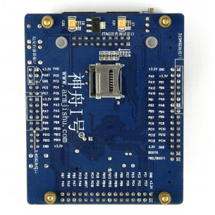
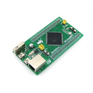
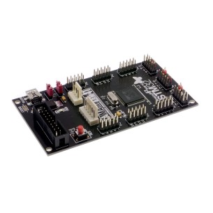
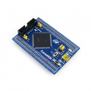
Waveshare Core429I is a PCB with STM32F429IGT6 microcontroller, contains necessary elements for microcontroller operation, all GPIOs connected to goldpin connectors
Waveshare Core429I is a PCB with a STM32F429IGT6 microcontroller, designed to build prototype devices with this processor. It is an ideal PCB to start working with STM32F4 series microcontrollers.
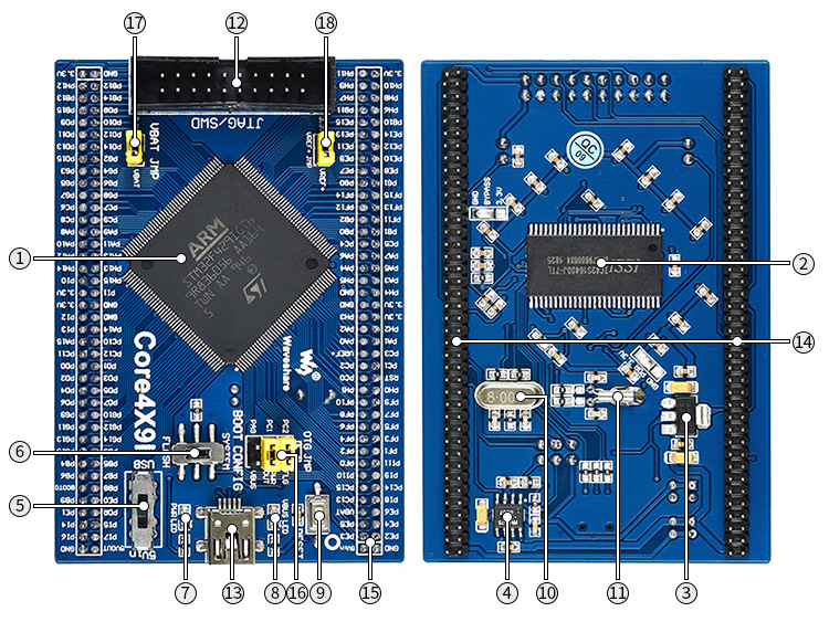
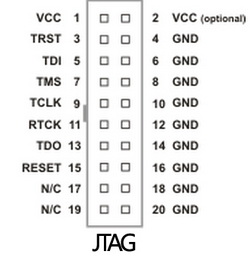
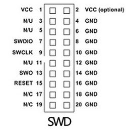
The board has no programmer! It must be purchased separately. The interface for programming and debugging the microcontroller program is JTAG / SWD.
Manufacturer BTC Korporacja sp. z o. o. Lwowska 5 05-120 Legionowo Poland sprzedaz@kamami.pl 22 767 36 20
Responsible person BTC Korporacja sp. z o. o. Lwowska 5 05-120 Legionowo Poland sprzedaz@kamami.pl 22 767 36 20
ARM Cortex-M4 CPU, 1024kB Flash, 192kB RAM, USB OTG FS+HS, 2xCAN, 4xUART, 3xI2C, 3xSPI, ADC, DAC, STM, LQFP64, RoHS
No product available!
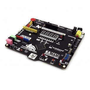
The starter kit is equipped with a STM32F373VCT6 microcontroller (256 MB Flash, Cortex-M4), with a built-in ST-Link / V2 programmer-debugger, has a TFT LCD display and a full set of connectors.
No product available!
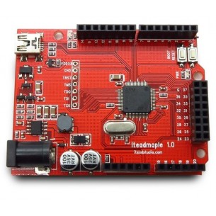
Microcontroller board based on Leaf Maple, STM32F103RB, USB, RoHS
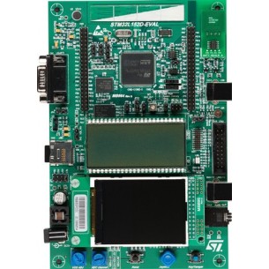
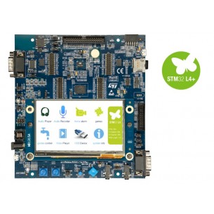
STM32L152D-EVAL is an advanced evaluation kit with the STM32L152ZDT6 microcontroller, integrating a wide range of peripherals and displays. It enables full testing of the chip’s capabilities and the development of low-power applications with access to multiple communication interfaces and diagnostic tools.
The tile has, among others SMT32F103RBT6 microcontroller from STMicroelectronics, Prolific PL-2303 converter and 2.2 "LCD color display with 176 x 220 px resolution. EB-STM32_09_LCD2.2
No product available!
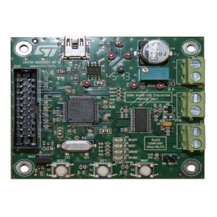
Development kit with STM32F105RBT6 microcontroller (128 KB Flash, 64 KB RAM) and L6470 stepper motor driver
No product available!
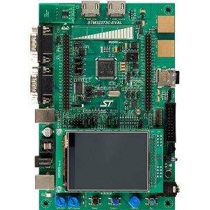
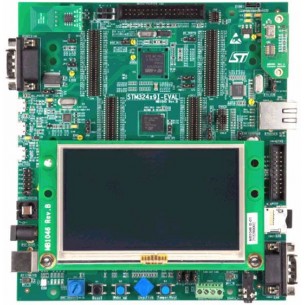
Evaluation board for STM32F429 line - with STM32F429NI MCU, STMStarter kit with STM32F429NIH6 microcontroller (2 MB Flash, Cortex-M4), with built-in ST-Link/V2 programmer-debugger, 4.3" TFT LCD display and full set of connectors
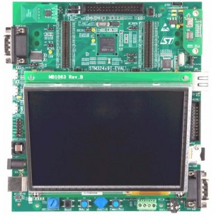
Starter kit with STM32F439NIH6 microcontroller (2 MB Flash, Cortex-M4), with built-in ST-Link/V2 programmer-debugger, 4.7" TFT LCD display and full set of connectors
No product available!
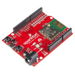
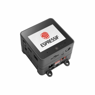
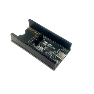
IoT development board the size of Arduino, equipped with an ARM Cortex-M3 processor (STM32F205) and a Wi-Fi communication module (with an integrated antenna and uFL connector). SparkFun DEV-13321
No product available!
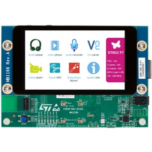
The STM32F7 discovery kit allows users to develop and share applications with the STM32F7 Series microcontrollers based on the ARM®Cortex®-M7 core.
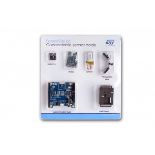
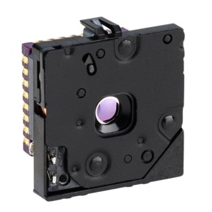
The STEVAL-STLKT01V1 is a comprehensive development kit designed to support and expand the capabilities of the SensorTile and comes with a set of cradle boards enabling hardware scalability
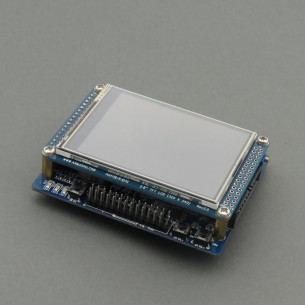
Development kit with STM32F103R8T6 microcontroller and 2.8 "TFT display with touch panel.
No product available!
Development kit with STM32L496ZGT6 microcontroller (ARM Cortex-M4 core) with a built-in ST-Link programmer. Extensive equipment, including: MEMS 6DoF sensor, motor controller, joystick, LED display, 8 LED diodes, RGB LED, audio amplifier, Flash memory QSPI 1 MB, microphone, Arduino connector
Single board computer with STM32F207VE microcontroller (ARM Cortex-M3, 512 kB Flash, 128 kB RAM, LQFP100).
The STM32L4R9I-EVAL evaluation set was designed to demonstrate the capabilities of the STM32L4R9AI microcontroller. Mounted connectors allow easy connection of extensions. The board also has a debugger / ST-LINK / V2-1 programmer. STM32L4R9I-EVAL
No product available!
Waveshare Core429I is a PCB with STM32F429IGT6 microcontroller, contains necessary elements for microcontroller operation, all GPIOs connected to goldpin connectors
Waveshare Core429I is a PCB with STM32F429IGT6 microcontroller, contains necessary elements for microcontroller operation, all GPIOs connected to goldpin connectors