


")
")

zł365.91 tax excl.
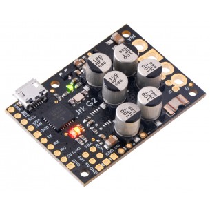
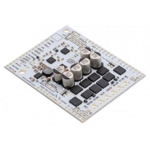
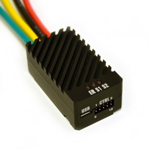
This powerful motor controller makes closed-loop speed or position (but not both!) control of a brushed DC motor easy, with quick configuration over USB using our free software. It supports five control interfaces: USB, TTL serial, I²C, analog voltage (potentiometer), and hobby radio control (RC).
This version offers a wide 6.5 V to 30 V operating range and can deliver continuous output currents up to 19 A without a heat sink.
With integrated support for analog voltage or tachometer (frequency) feedback, the second-generation G2 family of Jrk motor controllers makes it easy to add closed-loop control of speed or position (but not both!) of a single brushed DC motor to a variety of projects. These versatile, general-purpose modules support five different control interfaces: USB for direct connection to a computer, TTL serial and I²C for use with a microcontroller, RC hobby servo pulses for use in an RC system, and analog voltages for use with a potentiometer or analog joystick. They also offer many settings that can be configured using our free configuration software utility for Windows, Linux, and macOS. This software simplifies initial setup of the device and allows for in-system testing and monitoring of the controller via USB (a micro-B USB cable is required to connect the Jrk G2 to a computer).
The table below lists the members of the Jrk family, including the original versions, and shows the key differences among them.
| Jrk 21v3 | Jrk 12v12 | Jrk G2 21v3 | Jrk G2 18v19 | Jrk G2 24v13 | Jrk G2 18v27 | Jrk G2 24v21 | |
|---|---|---|---|---|---|---|---|
| Recommended max operating voltage: |
28 V(1) | 16 V | 28 V(1) | 24 V(2) | 34 V(3) | 24 V(2) | 34 V(3) |
| Max nominal battery voltage: |
24 V | 12 V | 24 V | 18 V | 28 V | 18 V | 28 V |
| Max continuous current (no additional cooling): |
2.5 A* | 12 A | 2.6 A | 19 A | 13 A | 27 A | 21 A |
| USB, TTL serial, Analog, RC control: |
 |
|
|
|
|
|
|
| I²C control: | |
|
|
|
|
||
| Hardware current limiting: | |
|
|
|
|||
| Dimensions: | 1.35″ × 1.35″ | 1.85″ × 1.35″ | 1.0″ × 1.2″ | 1.4″ × 1.2″ | 1.7″ × 1.2″ | ||
| 1 Transient operation (< 500 ms) up to 40 V. 2 30 V absolute max. 3 40 V absolute max. * Reduced from “3 A” based on newer, more stringent tests. The value now is directly comparable to the rating for the newer G2 21v3. |
|||||||
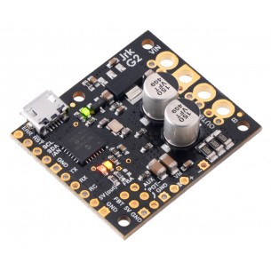
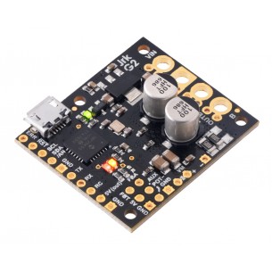
The Jrk G2 18v19 operates from 6.5 V to 30 V and can deliver a continuous output current of 19 A without a heat sink. Note that 30 V is the absolute maximum for this controller; the maximum recommended operating voltage is 24 V, and the maximum recommended nominal battery voltage is 18 V. For applications using higher voltages (such as 24 V batteries), we recommend the higher-voltage Jrk G2 24v13 or Jrk G2 24v21.
If you need to identify which version you have, you can just plug it into a computer through USB and the Jrk software will tell you. For quick visual identification without a computer, you can distinguish this version from the identically sized Jrk G2 24v13 by the number 150 on top of the tall silver electrolytic capacitors.
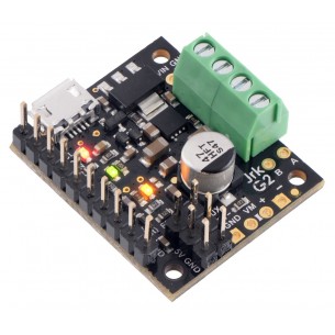
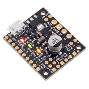
Pieces from the 0.1″ header strip can be soldered into the small holes on the logic connection side of the board to enable use with solderless breadboards, perfboards, or 0.1″ connectors, or you can solder wires directly to these holes for the most compact installation.The Jrk ships with a 0.1″ breakaway male header strip and two 2-pin 5mm terminal blocks. You can solder the terminal blocks to the four large through-holes to make your motor and motor power connections (see our short video on terminal block installation), or you can solder an 8-pin piece of the 0.1″ header strip into the smaller through-holes that border these larger holes. Note, however, that the terminal blocks are only rated for 16 A, and each header pin pair is only rated for a combined 6 A, so for higher-power applications, thick wires should be soldered directly to the board.
Note: A USB A to micro-B cable (not included) is required to connect the Jrk G2 to a computer for initial configuration.
The Jrk G2 family features a number of improvements compared to our original two Jrk motor controllers (21v3 and 12v12). Most importantly, the Jrk G2 controllers support both higher operating voltages and larger output currents while being even more compact than their predecessors. Other new features include:
The Jrk G2 controllers are not drop-in replacements for the original Jrk controllers because of differences in their form factors and pin arrangements, although wiring changes should be straightforward. The Jrk G2 serial protocol is compatible with (and generally a superset of) the original Jrk serial protocol, so in many cases, serial interface software running on a microcontroller or computer will not need to be modified to work with a Jrk G2.
| Motor channels: | 1 |
|---|---|
| Control interface: | USB; non-inverted TTL serial; I²C; RC servo pulses; analog voltage |
| Minimum operating voltage: | 6.5 V |
| Maximum operating voltage: | 30 V2 |
| Continuous output current per channel: | 19 A3 |
| Maximum PWM frequency: | 20 kHz |
| Reverse voltage protection?: | Y |
| Version: | G2 18v19 (30 V max, 19 A max continuous) |
| Connectors soldered?: | N |
| Size: | 1.2″ × 1.4″ × 0.42″1 |
|---|---|
| Weight: | 6.5 g1 |
Data sheet
Manufacturer BTC Korporacja sp. z o. o. Lwowska 5 05-120 Legionowo Poland sprzedaz@kamami.pl 22 767 36 20
Responsible person BTC Korporacja sp. z o. o. Lwowska 5 05-120 Legionowo Poland sprzedaz@kamami.pl 22 767 36 20
DC motor driver with voltage 6.5..40V and maximum continuous current 21A. It has the ability to easily implement the feedback loop and numerous control interfaces. Polol 3149
No product available!
DC motor driver with voltage 4.5..28V and maximum continuous current of 2.6A. It has the ability to easily implement the feedback loop and numerous control interfaces. Polol 3143
No product available!
DC motor driver with voltage 4.5..28V and maximum continuous current of 2.6A. It has the ability to easily implement the feedback loop and numerous control interfaces. Polol 3142
No product available!
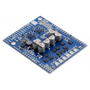
This shield makes it easy to control two high-power DC motors with your Arduino or Arduino-compatible board. Its twin discrete MOSFET H-bridges support a wide 6.5 V to 30 V operating range and are efficient enough to deliver a continuous 18 A without a heat sink.
Pololu Dual G2 High-Power Motor Driver 18v22 is an extension that allows you to control two DC motors designed for Arduino tiles. The motor can be supplied with 6.5 ... 30V voltage and can draw up a maximum current of 22A. Polol 2517
No product available!
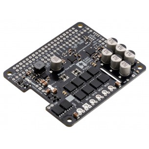
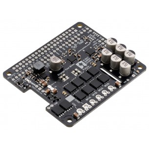
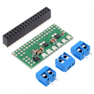
Pololu Dual G2 High-Power Motor Driver 24v18 is an extension that allows you to control two DC motors designed for Raspberry Pi. The motors can be supplied with 6.5-36V voltage and can draw a maximum current of 18A. Pololu 3756
No product available!
Pololu Dual G2 High-Power Motor Driver 18v22 is an extension that allows you to control two DC motors designed for Raspberry Pi. The motors can be powered with 6.5-30V and draw up a maximum current of 22A. Pololu 3754
No product available!
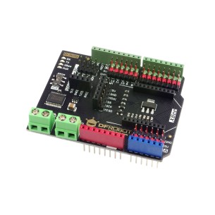
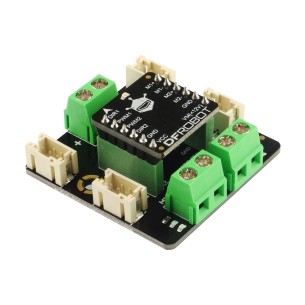
Gravity: IO Expansion & Motor Driver Shield is an Arduino compatible expansion board that provides digital I / O ports, analog I2C, SPI and UART interfaces, as well as a DC motor driver. DFRobot DFR0502
The RoboClaw Solo motor controllers from Basicmicro (formerly Ion Motion Control) can control a single brushed DC motor using USB serial, TTL serial, RC, or analog inputs. An integrated quadrature decoder make it easy to create a closed-loop speed control system.
No product available!
The RoboClaw Solo motor controllers from Basicmicro (formerly Ion Motion Control) can control a single brushed DC motor using USB serial, TTL serial, RC, or analog inputs. Pololu 3291
No product available!
2x1.2A DC Motor Driver is a dual controller of DC motors with a Gravity connector, supplied with 2.5 ... 12V voltage with a maximum current consumption of 1.2A (3.2A peak) per channel. DFRobot DRI0044-A
2x1.2A DC Motor Driver is a dual controller of DC motors powered with 2.5 ... 12V voltage with a maximum current consumption of 1.2A (3.2A peak) per channel. DFRobot DRI0044
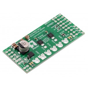
Dual MAX14870 Motor Driver is a dual DC motor controller compatible with the Arduino standard that allows you to control two DC motors with 4.5 ... 36V continuous current of 1.7A. Polol 2519
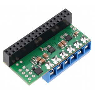
Dual MAX14870 Motor Driver is a dual DC driver compatible with Raspberry Pi that allows you to control two DC motors with 4.5-36V continuous current of 1.7A. Pololu 3759
ual MAX14870 Motor Driver is a dual DC motor driver compatible with the Raspberry Pi standard that allows you to control two DC motors with 4.5 ... 36V continuous current of 1.7A. Pololu 3758
This powerful motor controller makes closed-loop speed or position (but not both!) control of a brushed DC motor easy, with quick configuration over USB using our free software. It supports five control interfaces: USB, TTL serial, I²C, analog voltage (potentiometer), and hobby radio control (RC).
DC motor driver with voltage 6.5 ... 40V and maximum continuous current 13A. It has the ability to easily implement the feedback loop and numerous control interfaces. Polol 3147
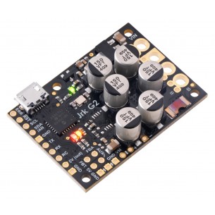
DC motor driver with voltage 6.5..30V and maximum continuous current 27A. It has the ability to easily implement the feedback loop and numerous control interfaces. Polol 3148
No product available!
DC motor driver with voltage 6.5..40V and maximum continuous current 21A. It has the ability to easily implement the feedback loop and numerous control interfaces. Polol 3149
No product available!
This powerful motor controller makes closed-loop speed or position (but not both!) control of a brushed DC motor easy, with quick configuration over USB using our free software. It supports five control interfaces: USB, TTL serial, I²C, analog voltage (potentiometer), and hobby radio control (RC).