


- Out-of-Stock


Hans-Jürgen Riehl, Anton Herner
The manual presents the issues of electrical engineering and automotive electronics, starting from the reminder of the basic concepts of electricity, and on the discussion of electronic control and control systems in modern cars. All systems and devices of electrical and electronic equipment, including data transmission systems (CAN buses, LIN, MOST, Bluetooth), also satellite navigation systems (GPS), telephone in the car and telematics issues are discussed. The eighth edition has been extended with information on: hybrid constructions including full, incomplete and micro-hybrid propulsion; the latest solution for data transmission networks in cars, ie the Flex Ray bus; gas as an alternative fuel and additional heating devices in cars.
Recipients of the book: university students with a car's direction, students of medium school cars and everyone interested in electrotechnics and car electronics.
Table of Contents:
Foreword 13
1. Basic concepts of electricity 15
1.1. The structure of the atom 15
1.2. Voltage 16
1.3. Current 17
1.4. Resistance 17
1.5. Possibilities of generating tension 18
1.6. The effects of electric current 19
1.7. Security regulations 20
1.7.1. Influence of electric current on a human being 20
1.7.2. First aid with electric shock 21
1.8. Types of voltage 21
2. Wiring diagrams 24
2.1. Components and construction of the electrical circuit 24
2.2. Graphic symbols 26
2.3. Ideological schemes 29
2.3.1. Connection diagram 29
2.3.2. Circuit diagram 30
2.4. Marking of electrical devices 30
2.5. Terminal designations 30
2.6. Electrical diagrams 31
2.6.1. Examples of schemes for a Volkswagen 31 car
2.6.2. Examples of schemes for a Ford 36 car
2.7. Place of mounting elements in a car 41
3. Measurements with a universal meter 44
3.1. Types of meters 44
3.2. Markings on universal analog meters 46
3.3. Markings on universal digital meters 47
3.4. The tolerance ranges of universal meters 49
3.4.1. Analog meters 49
3.4.2. Universal digital meters 50
3.5. Searching for faults using a voltmeter 50
3.6. Searching for faults using an ammeter 55
3.7. Searching for faults by measuring resistance 58
3.8. Summary: voltage, intensity and resistance measurements 64
3.9. Working with fault finding programs 65
3.9.1. Searching for faults in a Volkswagen 65 car
3.9.2. Searching for faults in a Ford 69 car
4. Basics of electrical engineering 74
4.1. Ohm's Law 74
4.2. Voltage losses 75
4.2.1. Voltage in a closed electrical circuit 75
4.2.2. Voltage in the open electrical circuit 76
4.3. Electric power 77
4.4. Resistance of the guide 79
4.5. Parallel and serial connections 80
4.5.1. Serial connection 80
4.5.2. Parallel connection 82
4.5.3. Overview 84
4.6. Mixed circuits 85
4.6.1. Extended serial connection 85
4.6.2. Extended parallel connection 87
4.7. Voltage divider, potentiometer 88
4.7.1. Unloaded voltage divider 88
4.7.2. Loaded voltage divider 89
4.8. Resistors depending on temperature 89
4.8.1. PTC resistors 89
4.8.2. NTC 93 resistors
4.9. Capacitor 94
4.9.1. Capacitor as electrical storage 94
4.9.2. Direction of current flow 94
4.9.3. Construction 95
4.9.4. Principle of operation 95
4.9.5. Charging and discharging history 96
4.9.6. Capacitor in an alternating current circuit 98
4.9.7. Capacitor as an anti-interference element in a car 98
4.10. Inductance 99
4.10.1. Magnetism 99
4.10.2. Electromagnetic induction 103
4.10.2.1. Motion induction 103
4.10.2.2. Resting induction 105
4.10.3. Coil 106
4.10.3.1. Self-induction after switching on the coil 106
4.10.3.2. Self-induction after disconnecting the coil 108
4.10.4. Electric engine and generator 110
4.10.4.1. Principle of operation of an electric motor 110
4.10.4.2. Principle of the generator 112
4.10.5. Relay 115
4.10.5.1. Principle of operation 115
4.10.5.2. Types of relays 118
4.10.5.3. Construction of reed relay 118
4.10.5.4. Examples of applications of reed relays in a car 119
4.10.5.5. Searching for a fault in the circuit with relay 121
5. Basic electronic components 126
5.1. Diode 126
5.1.1. Diode as an electric valve 126
5.1.2. Checking the diode 126
5.1.3. The use of a diode as an alternating current rectifier 128
5.1.4. Bridge system in a three-phase AC generator 129
5.1.5. Diode for disconnecting the electrical circuit 132
5.1.6. Diode for limiting the excitation voltage 13
5.1.7. Determination of diodes 133
5.2. Zener diode 133
5.2.1. Properties 134
5.2.2. Zener diode in the overvoltage protection relay 134
5.2.3. Zener diode as a straightening diode in a three-phase generator 135
5.3. Light-emitting diode (LED) 135
5.3.1. Properties 136
5.3.2. Construction 137
5.3.3. Application examples 139
5.4. Photodiode 142
5.4.1. Properties of the photodiode 143
5.4.2. Application examples photodiode 144
5.4.2.1. Rain and light sensor 144
5.4.2.2. Solar radiation sensor 146
5.4.2.3. Self-healing inner mirror 147
5.4.2.4. Non-contact temperature measurement 148
5.5. Transistor 150
5.5.1. Transistor as a control element 151
5.5.2. Comparison of transistor with relay 152
5.5.3. Transistor as an amplifier 153
5.5.4. Pulse duration ratio 155
6. System analysis and signal flow patterns 158
6.1. Functional analysis 158
6.2. The car as a system 159
6.3. Signal flow diagram 160
7. Basics of digital technology 162
7.1. Analog and digital signals 162
7.2. The principle of analogue transmission 164
7.2.1. Problems of analogue transmission 165
7.2.2. Examples of analogue transmission 165
7.3. The logic of basic digital connections 167
7.4. Overview of basic logic functions 170
7.5. A logical element that processes data 171
7.5.1. Signal level 172
7.5.2. The signal level in the car 173
7.6. Basic logic functions 173
7.6.1. Logical product 173
7.6.2. The logical sum 175
7.6.3. Logical negation 176
7.6.4. Summary 178
7.6.5. The abbreviations 178 used
7.6.6. Selected graphic symbols of logic elements 179
7.6.7. Example 179
7.7. Complex logical elements 181
7.8. Binary system 182
8. Data transmission in the car 184
8.1. Examples 185
8.2. Information processing in the control device 187
8.3. Analog-digital converter 188
8.4. Plug connections with the weak point of the system 190
8.5. Data transmission via data bus 190
8.6. Self-diagnosis 191
8.6.1. Sensor monitoring (eg cooling liquid temperature) 193
8.6.2. Supervising the adjuster (eg idling regulator) 194
8.7. Diagnostic data transmission bus 196
8.8. Onboard electrical installation and load management 203
9. Control and regulation 211
9.1. The difference between control and regulation 211
9.1.1. Control chain 211
9.1.2. Control circuit 211
9.2. Control 212
9.2.1. Control definition 212
9.2.2. Control chain links 212
9.2.3. Input and output values of the control chain 212
9.2.4. Types of control by signal type 214
9.2.5. Binary control 215
9.2.6. Analog control 216
9.2.7. Digital control 217
9.2.8. Control types by type of signal processing 218
9.3. Adjusting 219
9.3.1. Man as a regulator in the regulation circuit 219
9.3.2. Definition of regulation 220
9.3.3. Block diagram of the control circuit 221
9.3.4. Components of the control system 222
9.3.5. Control circuit 223
9.3.6. Types of regulators 223
9.3.7. Transition States 224
9.3.8. Current adjustment 225
9.3.9. Idle speed control 226
9.3.10. Venting the fuel tank 229
9.4. Adaptive control systems 231
9.4.1. Adaptation based on lambda 232 regulation
9.4.2. Diagnostic problems resulting from adaptation 234
10. Workshop oscilloscope 235
10.1. Analog and digital representation of signals 235
10.2. DC / AC coupling 236
10.3. Y-axis 237
10.4. X axis 237
10.5. Trigger pulse 239
10.5.1. The trigger pulse level 239
10.5.2. Flank of the trigger pulse 240
10.6. Images of typical signals from sensors 241
10.7. Checking the generator 242
10.7.1. Harmonic signals 242
10.7.2. The effect of the coupling type on the image 243
10.7.3. Examples of faults detected during test 244
11. Data transmission systems 246
11.1. Development of electronic car systems 246
11.2. The necessity of using a data transmission network 247
11.3. Basic concepts 249
11.3.1. Types of data transmission network 250
11.3.2. Basics of digital data transmission 252
11.4. CAN bus 253
11.4.1. Signal transmission 253
11.4.2. Message format 257
11.4.3. Diagnostics 260
11.5. LIN 264 bus
11.6. Optical data transmission networks 268
11.6.1. Transmission of optical fiber signals 268
11.6.2. MOST Bus 270
11.6.3. MOST 271 bus diagnostics
11.6.4. Bus Byteflight 273
11.7. Bluetooth 275 network
11.8. Flex Ray 276
11.9. Examples of using the data transmission network in a car 278
11.10. Programming, coding, personalization, individualization 283
12. Ignition systems 289
12.1. Non-contact ignition control 289
12.1.1. Advantages 289
12.1.2. Construction and operation 290
12.1.3. Inductive signal transistor firing 291
12.1.4. The signal is emitted by the Hall sensor 292
12.1.5. Detection of ignition-controlled ignition faults 294
12.2. Electronic ignition 297
12.2.1. Functional diagram with the inputs and outputs of the control device 298
12.2.2. The most important input signals for calculating KWZ 299
12.2.3. Additional input signals 301
12.2.4. Output signals and troubleshooting tips 303
12.3. Ignition completely electronic 304
12.3.1. Construction and advantages of static high voltage distribution 304
12.3.2. Static high voltage distribution via bipolar 305 coils
12.3.3. Feedback on the 306 static ignition charge
12.3.4. Troubleshooting Tips 307
13. Injection systems 308
13.1. Continuous injection (K-Jetronic system) 308
13.1.1. Description of functions and components of the 308 system
13.1.2. Components and their functions 310
13.1.3. Additional, electrically controlled elements of the 316 system
13.1.4. Electrical scheme 318
13.1.5. K-Jetronic system with lambda 319 regulation
13.2. The KE-Jetronic 320 system
13.2.1. Differences in relation to the K-Jetronic 321 system
13.2.2. Input signals and their meaning for electronic control 321
13.2.3. Adjusting the injection dose via the electro-hydraulic pressure regulator 324
13.3. Intermittent injection (L-Jetronic system) 325
13.3.1. A general description of the operation of the 325 system
13.3.2. Components and their functions 326
13.3.3. Functions of the control device 335
13.3.4. General electrical scheme of the 338 system
13.4. Mono-Jetronic system 339
13.4.1. Fuel supply circuit 339
13.4.2. Input signals to determine operating conditions 342
13.4.3. Operation of the control device, output signals 344
13.5. Lambda control 346
13.5.1. Adaptation of the composition of the mixture 348
13.5.2. Construction and operation of the lambda sensor 349
13.5.3. Lambda probe with a titanium dioxide cartridge 350
13.5.4. Planar lambda sensor 352
13.5.5. Broadband planar oxygen sensor 352
13.6. Electronically regulated injection systems in diesel engines 353
13.6.1. General information, layout review 353
13.6.2. Input signals and their effect on the operation of the 354 system
13.6.3. Control of various injection pumps and other output signals 357
13.6.4. Direct injection in diesel engines 362
13.6.4.1. Radial manifold injection pumps 362
13.6.4.2. Systems with pump injectors (UIS) and individual injection pumps (UPS) 366
13.6.4.3. Cylindrical Common Rail 366 injection system
13.6.5. Ways to improve the purity of exhaust gases in cars with diesel engines 372
14. Integrated injection-ignition systems and current requirements 375
14.1. General information 375
14.2. Additional functions in various Motronic 376 solutions
14.3. Digital engine control systems with injection to the inlet pipe 379
14.4. Digital engine control systems with direct petrol injection 384
14.5. European on-board diagnostics (E-OBD) 386
14.6. Gas as an alternative fuel 389
14.6.1. Introductory information 389
14.6.2. Car installation for natural gas 391
14.6.3. Automotive gas installations as an accessory 395
14.6.4. Legal regulations 397
15. Dynamics driving control systems 398
15.1. Anti-lock system (ABS) 398
15.1.1. Basic functions and general structure of ABS 398
15.1.2. Wheel speed sensors 399
15.1.3. Closed system with solenoid valves 3/3 401
15.1.4. Open system with solenoid valves 2/2 404
15.1.5. Closed circuit with 2/2 solenoid valves 406
15.1.6. ABS in 409 motorcycles
15.2. Anti-slide system (ASR) 412
15.2.1. Anti-slip system with electromagnetic valves 3/3 413
15.2.2. Anti-slip system with solenoid valves 2/2 418
15.3. Stability control 422
15.3.1. Description of the stabilization system 422
15.3.2. Input and output signals 425
15.4. Adjustable differential locks 432
15.4.1. Input and output signals in control device 433
15.4.2. Electrohydraulic and electromagnetic locks 435
15.4.3. The electric circuit of the electromagnetic lock in the four-wheel drive system 437
15.5. Electronic adjustment of shock absorbers 439
16. Passive safety systems 443
16.1. Introduction 443
16.2. Construction and operation of front gasbags 444
16.3. System supervision and safety regulations 451
16.4. Side gasbags 456
16.5. 457 gas curtains
16.6. Pyrotechnic belt tensioners 459
16.7. Compact pillow (eurobag) 463
16.8. An example of a complete 466 system
17. Theft protection systems 467
17.1. Electronic protection against unauthorized use 467
17.1.1. Protection with the transponder before starting the car 468
17.1.2. Installation of the immobilizer in a factory unprotected vehicle 471
17.2. Alarm installations 472
17.2.1. General description of the system 472
17.2.2. Input signals and components of the installation 474
17.2.3. Output signals and electrical diagram of the 481 alarm system
18. Systems that increase driving comfort 484
18.1. Control of heating and air conditioning 484
18.1.1. Description of operation and structure of the system 484
18.1.2. The principle of air conditioning 486
18.1.3. Input signals 488
18.1.4. Output signals and operation 489
18.1.5. Schematic diagram 495
18.2. Electronic gearbox control 499
18.2.1. System description 499
18.2.2. Input and output signals 501
18.2.3. Infinite automatic gearbox 507
18.3. Electronic clutch control and automated gear box 510
18.3.1. Electronic clutch control 510
18.3.2. Automated gearbox 513
18.4. 516 speed regulation
18.4.1. Description of the system 516
18.4.2. Components, input and output signals 517
18.4.3. Adaptive travel speed adjustment 520
18.5. Electronic distance measurement (parking assistant) 525
18.6. Central locking of the door 531
18.6.1. Central locking of doors with pneumatic actuators 531
18.6.2. Central locking of doors with electric actuators 536
18.6.3. Comfortable access to the car 542
18.7. Electric window control 544
18.8. Electric roof control 548
18.9. Electrical adjustment of external mirrors 550
18.10. Electric seat adjustment 552
18.11. Electric seat and mirror adjustment with memory 554
18.12. Electric steering column position adjustment 557
18.13. Additional heating device 559
18.13.1. Overview of structural solutions 559
18.13.2. Operation of the heating device 561
18.13.3. Assembly instructions and legal regulations 562
18.13.4. Diagnosis and electrical scheme of the parking heater 564
19. Integrated driver information systems 567
19.1. Introduction 567
19.2. Inputting commands and input signals 568
19.3. Messages and playback 572
19.4. Satellite navigation systems 573
19.4.1. Introductory information 573
19.4.2. Establishing a position and calculating a route 5741
9.4.3. Construction of a GPS navigation system in a 576 car
19.4.4. Possible functions 579
19.4.5. Possible faults and their causes 581
19.5. Phone in the car 583
19.5.1. Development of mobile telephony 583
19.5.2. Principles of operation and applied technologies 583
19.5.3. Examples of solutions and development stages 586
19.5.3.1. Fixed telephones, late 90s of the 20th century 586
19.5.3.2. Mobile phone integrated with the car 587
19.5.3.3. Installing a mobile phone as an accessory 589
19.5.3.4. The telephone is permanently mounted, integrated with the driver information system, as of the beginning of 2000, 591
19.5.3.5. The phone in bluetooth technology integrated with the driver information system 592
19.6. Telematics 593
19.6.1. Communication telematics 594
19.6.2. Alarm call function 596
19.6.3. Online services 597
19.6.4. Telematic functions regarding only the car 599
20. Hybrid constructions 600
20.1. Definition 600
20.2. Introductory information 600
20.2.1. Breakdown by construction 600
20.2.1.1. 600 parallel hybrid drive
20.2.1.2. Series 601 hybrid drive
20.2.1.3. Mixed or branched hybrid drive 601
20.2.1.4. Hybrid drive charged from the mains (Plug-In-Hybrid) 602
20.2.2. Breakdown by the degree of electrification of the vehicle 602
20.2.2.1. Micro Hybrid drive 602
20.2.2.2. Incomplete hybrid drive (Mild Hybrid) 603
20.2.2.3. Full hybrid drive 605
20.3. Driving auxiliary teams on Full Hybrid 607 cars
20.4. The advantages and disadvantages of the 608 hybrid drive
20.4.1. Collaboration of a gasoline engine with an electric motor 608
20.4.2. The benefits of 608 hybrid cars
20.4.3. Disadvantages of hybrid cars 609
20.5. The Toyota Prius is an example of a serial-parallel 610 hybrid drive
20.5.1. Components of the drive system (Fig. 20.13) 610
20.5.2. High voltage batteries (HV) 611
20.5.2.1. Nickel-metal hydride (NiMH) battery 611
20.5.2.2. Lithium-ion batteries (Li-Ion) 613
20.5.3. Power distribution 615
20.5.4. Construction and operation of AC synchronous machine 616
20.5.5. Transducer (inverter, inverter) - figures 20.23 and 20.25 619
20.5.6. Electronic control device 620
20.5.7. Safety system for the Toyota Prius 621 hybrid drive
20.6. Cars with self-protected high voltage circuits 623
20.6.1. Self-insurance 623
20.6.2. Safety rules for cars with high voltage circuits 623
20.6.3. Technical conditions for safe operation of high voltage circuits 624
Source materials 626
Illustration sources 628
List of abbreviations 631
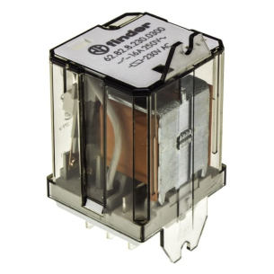
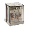
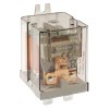
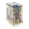
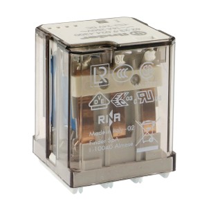
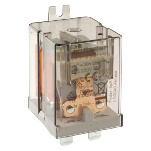
The Finder 62.82.8.230.0300 electromagnetic relay is a robust component for industrial electrical and automation applications, offering high reliability and high current capacity. Equipped with a 230V AC coil, it allows switching currents up to 16A at a voltage of 250VAC on each of the two independent contacts, making it ideal for controlling devices with high power consumption.
No product available!
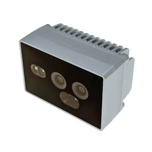
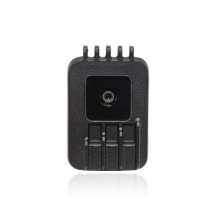
Industrial depth camera with ToF sensor, designed for precise detection up to 3 meters, ideal for applications such as pick-and-place, quality control or industrial automation. With IP65/IP67 sealing, active IR, PoE connectivity and 4 TOPS computing power (including 1.4 TOPS on AI), it offers reliable operation even in harsh environments. It supports CV and AI algorithms, remote control, standalone operation and multiple network protocols, making it a versatile tool for industry and robotics. Luxonis OAK-D SR PoE
No product available!
Uni-T UT387D is a compact detector for detecting metals, live wires and wood in walls, floors and ceilings. It allows precise location of objects at a depth of up to 80 mm (metals), 50 mm (wires) and 20 mm (wood), and its ergonomic housing, LCD display and automatic calibration ensure comfortable and accurate work.
No product available!
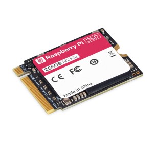
The Raspberry Pi SSD 256GB is a fast and reliable storage solution, ideal for demanding Raspberry Pi 5 applications, ensuring efficient handling of I/O-intensive tasks
No product available!
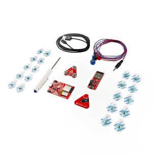
Kit for measuring muscle activity using electromyography (EMG). Contains everything you need from the MyoWare 2.0 ecosystem to test basic configurations in your applications. SparkFun KIT-25332
No product available!
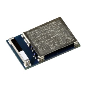
An advanced wireless communication module based on the Bluetooth 5.2 (Bluetooth® Low Energy, BLE) stack, which is designed using the powerful Nordic nRF5340 SoC. It provides GPIO, SPI, UART, TWI, I2C, PDM, PWM, ADC, NFC and USB interfaces for connecting peripherals and sensors. SparkFun WRL-25465
No product available!
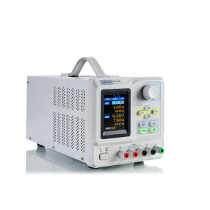
Programmable linear laboratory power supply with a 0-30 V and 0-5 A range, equipped with a 2.8" TFT-LCD screen and real-time voltage waveform display. It supports remote control (SCPI, LabView), save/recall settings, 4-wire measurement, and quiet cooling with a temperature-controlled fan. Thanks to its low noise level, compact housing, and safety features, it is ideal for service, R&D, and precise power supply of electronic systems. Siglent SPD1305X
No product available!
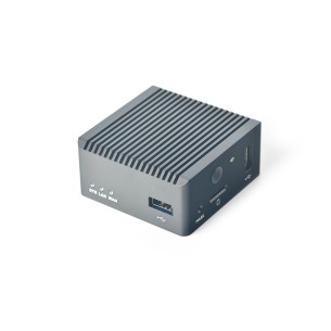
Compact mini computer with quad-core Rockchip RK3328 processor and 1GB DDR4 RAM, ideal for network applications and IoT projects. Equipped with 32GB of built-in eMMC memory and support for microSD cards up to 128GB, it provides flexible data storage. The device supports 1Gbps Ethernet, two USB 2.0 Host ports, two USB-C ports and an optional Wi-Fi module, making it a versatile solution for DIY projects, routers and servers. FriendlyELEC NanoPi R2S Plus
No product available!
Ethernet cable featuring a robust M12X connector on one end and a standard RJ45 connector on the other, providing flexibility for connecting to Series 2 PoE cameras. With an IP67 protection rating and compliance with IEC 61076-2-109, it is suitable for demanding applications
No product available!
Ethernet cable featuring a robust M12X connector on one end and a standard RJ45 connector on the other, providing flexibility for connecting to Series 2 PoE cameras. With an IP67 protection rating and compliance with IEC 61076-2-109, it is suitable for demanding applications.
No product available!
Ethernet cable featuring a robust M12X connector on one end and a standard RJ45 connector on the other, providing flexibility for connecting to Series 2 PoE cameras. With an IP67 protection rating and compliance with IEC 61076-2-109, it is suitable for demanding applications
No product available!
Ethernet cable featuring a robust M12X connector on one end and a standard RJ45 connector on the other, providing flexibility for connecting to Series 2 PoE cameras. With an IP67 protection rating and compliance with IEC 61076-2-109, it is suitable for demanding applications
No product available!
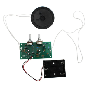
FM radio kit using the Si4820 and NCP2890. The board has pre-soldered circuits, making the assembly process easier for the user. To complete the radio, simply solder the remaining components, such as resistors and capacitors, and the radio offers tuning and volume control, with sound output from the included 66 mm speaker. The board is powered from 2.5 V to 5.5 V, which allows it to be used with both mains power and AA batteries, and the Si4820 circuit provides excellent radio reception quality. Kitronik 2157
No product available!
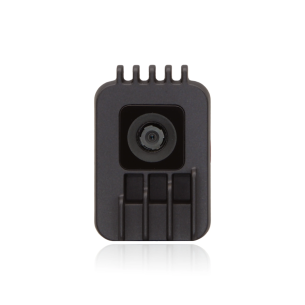
1MP AI camera that enables neural network processing and image analysis directly on the device, supporting AI models after conversion. Equipped with a 4 TOPS RVC2 architecture, with features such as distortion correction, 2D object tracking, and fixed focus, it is ideal for complex computer vision tasks with fast data transfer via USB-C. Luxonis OAK-1 Global Shutter
No product available!
13MP AI camera that enables neural network processing and image analysis directly on the device, supporting AI models after conversion. Equipped with a 4 TOPS RVC2 architecture, with features such as distortion correction, 2D object tracking, and fixed focus, it is ideal for complex computer vision tasks with fast data transfer via USB-C. Luxonis OAK-1 Lite Wide
No product available!
12MP AI camera that enables neural network processing and image analysis directly on the device, supporting AI models after conversion. Equipped with a 4 TOPS RVC2 architecture, with features such as distortion correction, 2D object tracking, and a fixed-focus lens, it is ideal for complex computer vision tasks with fast data transfer via USB-C. Luxonis OAK-1 Wide
No product available!
Hans-Jürgen Riehl, Anton Herner