
- Out-of-Stock


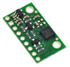
Pololu 2127
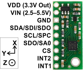
LSM303D 3D Compass and Accelerometer Carrier with Voltage Regulator
The LSM303D combines a digital 3-axis accelerometer and 3-axis magnetometer into a single package that is ideal for making a tilt-compensated compass. The six independent readings, whose sensitivities can be set in the ranges of Âą2 to Âą16 g and Âą2 to Âą12 gauss, are available through IÂ?C and SPI interfaces. This LSM303 carrier board includes a 3.3 V voltage regulator and integrated level shifters that allows operation from 2.5 to 5.5 V, and the 0.1" pin spacing makes it easy to use with standard solderless breadboards and 0.1" perfboards.
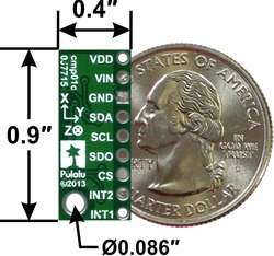  |
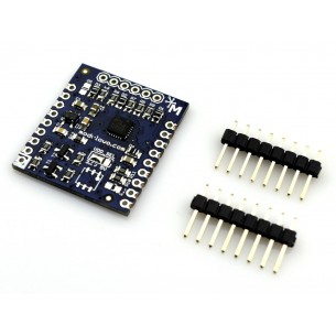
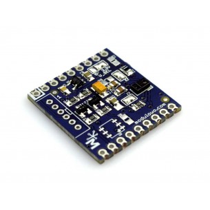
This board is a compact (0.4" A— 0.9") breakout board for ST’s LSM303D 3-axis accelerometer and 3-axis magnetometer; we therefore recommend careful reading of the LSM303D datasheet (1MB pdf) before using this product. The LSM303D is a great IC, but its small package makes it difficult for the typical student or hobbyist to use. It also operates at voltages below 3.6 V, which can make interfacing difficult for microcontrollers operating at 5 V. This carrier board addresses these issues by incorporating additional electronics, including a 3.3 V voltage regulator and level-shifting circuits, while keeping the overall size as compact as possible. The board ships fully populated with its SMD components, including the LSM303D, as shown in the product picture.
Compared to its predecessors, including the LSM303DLM and LSM303DLHC used on our earlier LSM303 compass and accelerometer carrier boards, the LSM303D features a number of improvements, such as a wider maximum magnetic sensing range (up to Âą12 gauss). Instead of appearing as two separate devices with distinct addresses like previous sensors, the LSM303D appears as a single unified IÂ?C device, and it also offers an SPI interface for additional flexibility.
This LSM303D carrier is not pin-compatible with our earlier LSM303 compass and accelerometer carriers (the pinout and the orientation of the sensor axes are different). It should still be usable as a replacement with the appropriate wiring changes, but changes in IÂ?C addresses and configuration registers mean that code written to interface with a different chip will need to be modified to work with an LSM303D.
The LSM303D has many configurable options, including dynamically selectable sensitivities for the accelerometer and magnetometer, a choice of output data rates, and two independently-programmable external inertial interrupt pins. The magnetometer and accelerometer can be individually turned on and off to save power. The six independent magnetic and acceleration readings (sometimes called 6DOF) are available through a digital interface, which can be configured to operate in either IÂ?C (TWI) or SPI mode; this data can be used for many applications, including making a tilt-compensated compass that can be used to determine headings regardless of how the board is inclined. (ST provides an application note (1MB pdf) that explains the details of making one, and an Arduino library containing an example application can be found in the Sample Code section below.)
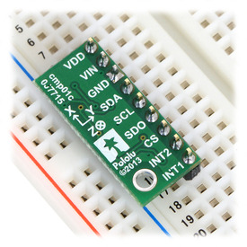
The carrier board includes a low-dropout linear voltage regulator that provides the 3.3 V required by the LSM303D, which allows the sensor to be powered from a 2.5–5.5 V supply. The regulator output is available on the VDD pin and can supply almost 150 mA to external devices. The breakout board also includes a circuit that shifts the IÂ?C clock and data lines to the same logic voltage level as the supplied VIN, making it simple to interface the board with 5 V systems, and the board’s 0.1" pin spacing makes it easy to use with standard solderless breadboards and 0.1" perfboards.
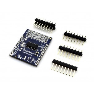
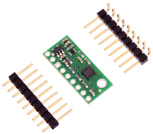
A 1A—9 strip of 0.1" header pins and a 1A—9 strip of 0.1" right-angle header pins are included, as shown in the picture below. You can solder the header strip of your choice to the board for use with custom cables or solderless breadboards, or you can solder wires directly to the board itself for more compact installations.
 |
The board has one mounting hole that works with #2 and M2 screws (not included).
A minimum of four connections are necessary to use the LSM303D: VIN, GND, SCL, and SDA. VIN should be connected to a 2.5–5.5 V source, GND to 0 volts, and SCL and SDA should be connected to an I�C bus operating at the same logic level as VIN. (Alternatively, if you are using the board with a 3.3 V system, you can leave VIN disconnected and bypass the built-in regulator by connecting 3.3 V directly to VDD.)
|
|
| PIN | Description |
|---|---|
| VDD | Regulated 3.3 V output. Almost 150 mA is available to power external components. (If you want to bypass the internal regulator, you can instead use this pin as a 3.3 V input with VIN disconnected.) |
| VIN | This is the main 2.5 V to 5.5 V power supply connection. The SCL/SPC and SDA/SDI level shifters pull the IÂ?C and SPI bus high bits up to this level. |
| GND | The ground (0 V) connection for your power supply. Your IÂ?C or SPI control source must also share a common ground with this board. |
| SDA/SDI/SDO | Level-shifted IÂ?C data line and SPI data in line (also doubles as SDO in 3-wire mode): HIGH is VIN, LOW is 0 V |
| SCL/SPC | Level-shifted IÂ?C/SPI clock line: HIGH is VIN, LOW is 0 V |
| SDO/SA0 | SPI data out line in 4-wire mode: HIGH is VDD, LOW is 0 V. This output is not level-shifted. Also used as an input to determine IÂ?C slave address (see below). |
| CS | SPI enable (chip select). Pulled up to VDD to enable IÂ?C communication by default; drive low to begin SPI communication. |
| INT2 | Programmable interrupt, a 3.3-V-logic-level output. This output is not level-shifted. |
| INT1 | Programmable interrupt, a 3.3-V-logic-level output. This output is not level-shifted. |
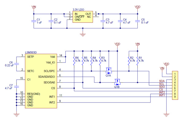 |
The above schematic shows the additional components the carrier board incorporates to make the LSM303D easier to use, including the voltage regulator that allows the board to be powered from a single 2.5–5.5 V supply and the level-shifter circuit that allows for I�C and SPI communication at the same logic voltage level as VIN. This schematic is also available as a downloadable PDF (162k PDF).
With the CS pin in its default state (pulled up to VDD), the LSM303D can be configured and its readings can be queried through the IÂ?C bus. Level shifters on the IÂ?C clock (SCL) and data lines (SDA) enable IÂ?C communication with microcontrollers operating at the same voltage as VIN (2.5–5.5V). A detailed explanation of the protocol can be found in the LSM303D datasheet (1MB pdf), and more detailed information about IÂ?C in general can be found in NXP’s IÂ?C-bus specification (371k pdf).
In IÂ?C mode, the sensor’s 7-bit slave address has its two least significant bits determined by the voltage on the SA0 pin. The carrier board pulls SA0 to VDD through a 4.7 kΩ resistor, making the least significant bits 01 and setting the slave address to 0011101b by default. If the selected slave address happens to conflict with some other device on your IÂ?C bus, or if you want to use two LSM303D sensors on the same bus, you can drive SA0 low to set the least significant bits to 10 (which sets the slave address to 0011110b).
The IÂ?C interface on the LSM303D is compliant with the IÂ?C fast mode (400 kHz) standard. In our tests of the board, we were able to communicate with the chip at clock frequencies up to 400 kHz; higher frequencies might work but were not tested.
To communicate with the LSM303D in SPI mode, the CS pin (which the board pulls to VDD through a 4.7 kΩ resistor) must be driven low before the start of an SPI command and allowed to return high after the end of the command. Level shifters on the SPI clock (SPC) and data in (SDI) lines enable SPI communication with microcontrollers operating at the same voltage as VIN (2.5 V to 5.5 V).
In the default 4-wire mode, the sensor transmits data to the SPI master on a dedicated data out (SDO) line that is not level-shifted. If the SPI interface is configured to use 3-wire mode instead, the SDI line doubles as SDO and is driven by the LSM303D when it transmits data to the master. A detailed explanation of the SPI interface on the LSM303D can be found in its datasheet (1MB pdf).
We have written a basic Arduino library for this LSM303 carrier board that makes it easy to interface this sensor with an Arduino. The library makes it simple to read the raw accelerometer and magnetometer data, and it has a function for computing the tilt-compensated heading for those looking to use this sensor as a tilt-compensated compass.
The datasheet provides all the information you need to use this sensor, but picking out the important details can take some time. Here are some pointers for communicating with and configuring the LSM303D that we hope will get you up and running a little bit faster:
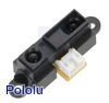 |
Sharp GP2Y0A21YK0F Analog Distance Sensor 10-80cm |
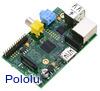 |
Raspberry Pi Model B, Revision 2.0 |
 |
L3GD20 3-Axis Gyro Carrier with Voltage Regulator |
Data sheet
Manufacturer BTC Korporacja sp. z o. o. Lwowska 5 05-120 Legionowo Poland sprzedaz@kamami.pl 22 767 36 20
Responsible person BTC Korporacja sp. z o. o. Lwowska 5 05-120 Legionowo Poland sprzedaz@kamami.pl 22 767 36 20
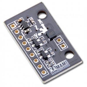
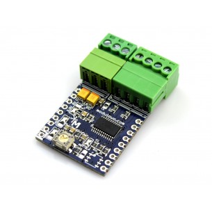
KAmodLSM6DS3 is a module that allows measurement of acceleration and angular velocity values. It has a built-in voltage stabilizer and level translators on SDA / SCL lines, thanks to which it can be used in 2.5-5.5V voltage systems
ADC analog-to-digital converter module allows voltage measurement and digital output, has built-in MCP3208 chip. MOD 59
No product available!
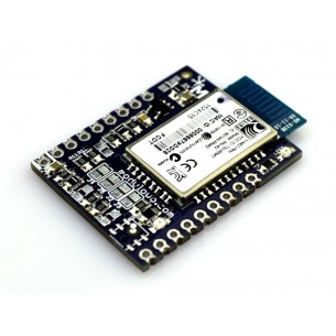
The module enables wireless communication using Bluetooth technology in version 2.1. It has a built-in RN-42 chip with UART interface. MOD 60
No product available!
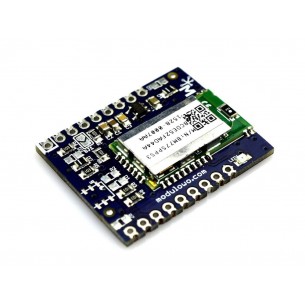
The module enables wireless communication using Bluetooth\'s Low Energy version 4.0. or Bluetooth BR / EDR, it has a built-in BM77SPPS3MC2 chip with a UART interface. MOD-62
No product available!
The module allows measuring the magnetic field in three XYZ planes, equipped with an HMC5883L sensor with an I2C interface. MOD-63
No product available!
The Explore magnetometer allows you to measure the magnetic field in three planes XYZ, equipped with a digital MAG3110 sensor. MOD 64
No product available!
Module for measuring position changes in space using a built-in sensor with 9 degrees of freedom, equipped with an LSM9DS0 system with a 3-axis accelerometer, a 3-axis gyroscope and a 3-axis magnetometer. MOD 65
No product available!
The plate allows the detection of gestures, similar objects at a distance of a few to several centimeters and the intensity of ambient light, equipped with an APDS-9960 system with an I2C interface. MOD-66
No product available!
The GPIO Expander board allows you to extend the project with an additional 16 I / O signal lines, equipped with an MCP23017 chip with an I2C interface. MOD-67
No product available!
Digital altimeter with barometer and temperature sensor, equipped with MPL3115A2 system with I2C interface. MOD-69
No product available!
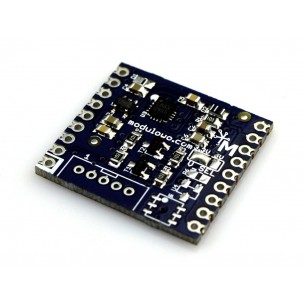
Bipolar stepper motor driver for speed and direction control with built-in A4982 system. MOD-70
No product available!
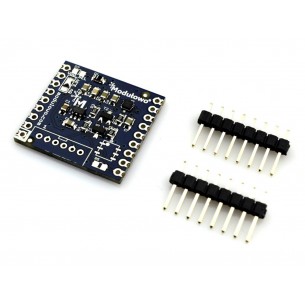
The board generates 16 PWM signals and communicates using the digital I2C interface, it has a built-in PCA9685 chip. MOD 71
No product available!
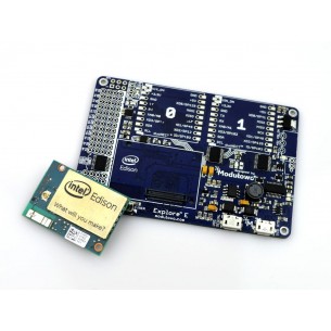
Extension kit for the Intel Edison computer module (with dual-core Intel Atom processor, Wi-Fi and Bluetooth), compatible with Arduino, Linux, C, C ++, Python, and JavaScript. MOD 76
No product available!
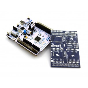
Adapter enabling easy and quick connection of Modulowo DuoNect expansion modules to selected STM32 Nucleo series platforms. MOD-78
No product available!
No product available!
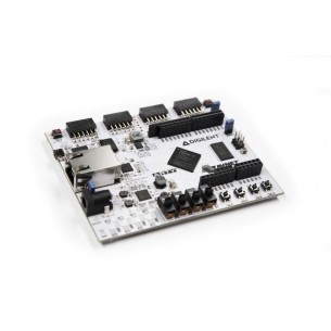
Arty is a ready-to-use development platform designed around the Artix-7™ Field Programmable Gate Array (FPGA) from Xilinx. 410-319
No product available!
No product available!
Pololu 2127