- Out-of-Stock
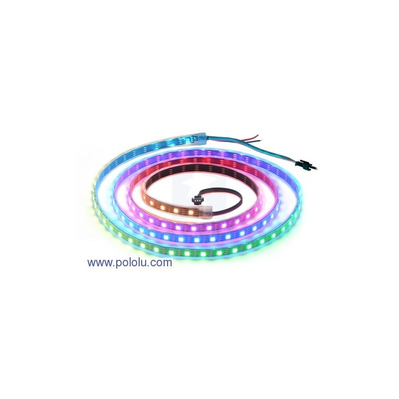
Addressable RGB 120-LED Strip, 5V, 2m (WS2812B)
This 2-meter long strip contains 120 RGB LEDs that can be used in a single RGB LED. The flexible, waterproof strip runs on 5 V and can be chained with an additional WS2812B strips to form a longer distance between each other. LED for shorter sections.
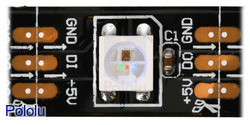 |
| Close-up of a segment of a WS2812B-based LED strip, with the red, green, and blue LEDs on at their dimmest setting. |
|---|
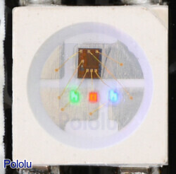 |
| Close up of a WS2812B, with the red, green, and blue LEDs on at their dimmest setting. |
|---|
These flexible RGB LED strips are an easy way to add complex lighting effects to a project. Each LED has an integrated driver that allows you to control the color and brightness of each LED independently. The combined LED / driver is a WS2812B (essentially an improved WS2811 LED driver integrated direct into 5050 RGB LED), which enables higher LED densities. In the picture, it can be connected to the LED, which can be connected to the LED.
We offer five different kinds of WS2812 LED strip with different LED densities and lengths. These ones have 30 LEDs per meter :
We also offer these denser WS2812 LED strips that have 60 LEDs per meter :
The WS2812-based LED strips in sell.
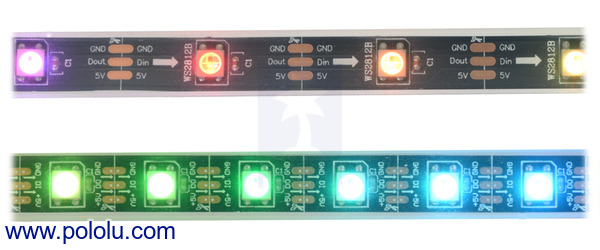 |
| LED side of the WS2812B-based addressable LED strips. The upper strip has 30 LEDs per meter and the lower strip has 60 LEDs per meter. |
|---|
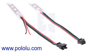 |
| The connectors and power wires for our WS2812B-based LED strips. On the left is the end of the end of the strip. |
|---|
Each LED strip has three connection points: the input connector, the auxiliary power wires, and the output connector. These can be seen in the picture, from left to right: auxiliary power wires, input connector, output connector. The strip uses 3-pin JST SM connectors.
The input is connected to the plastic connector, each separated by 0.1 ". The black wire is ground, the green wire is the power input.
The auxiliary power wires are connected with the stripped black and red wires. The black wire is ground, and the red wire is the power line. This is an alternate (and probably more convenient) connection for LED strip power.
The output connector is on the other end of the strip and mate it is designed with the input connector of another LED strip LED strips allow it to be chained. The black wire is ground, the green wire is the signal output.
All three black ground wires are electrically connected.
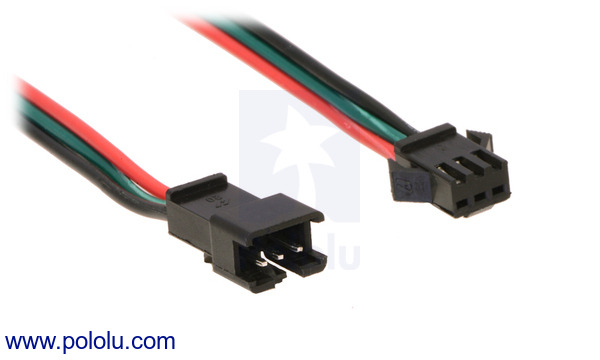 |
| A close-up of the JST SM connectors for our WS2812B-based LED strips. |
|---|
These LED strips ship with 5 flexible plastic brackets and 10 screws per meter. The brackets fit over the waterproof sheath and can be used to mount the LED strip. The LED strip also ships on a plastic reel.
|
|
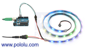 |
| Controlling an addressable RGB LED strip with an Arduino and powering it from a 5V wall power adapter. |
|---|
To control the LED strip from a microcontroller, your microcontroller should be connected to your microcontroller. The LED strip's ground (black) should be connected to the microcontroller's I / O line. The male connectors on the input jumper wires and wires with pre-crimped terminals. If you are connecting the LED strip to a breadboard or a typical Arduino with female headers, you would like to use male-female wires.
We generally recommend powering the LED strip using the auxiliary power wires. Our 5 V wall power adapters work well for powering these LED strips and a DC Barrel Jack is a 2-pin terminal block adapter can help you with the adapter and the strip. However, you might need a wire stripper to strip off some of the power wires.
It is convenient that the power wires are on the inside of the input. The power supply is connected to the microcontroller that is controlling. the LED strip. This means you can power up the microcontroller and LED strip from a single power supply.
Warning: The WS2812B seems to be more sensitive than our original TM1804-based LED strips. We recommend connecting the capacitor with at least 100 μF power to the input and use of the device (ESD) circuit is powered). If the strip does get damaged, it is often just the first LED that is broken; in such cases, cutting off the first segment and the resoldering the connector to the second segment of the strip back to life.
Each RGB LED draws approximately 50 mA when it is full brightness and powered at 5 V. This means that every 30 LEDs can turn on your LED strip could be drawing as much as 1.5 A. Be sure to select a power source that can handle your strip's current requirements.
There is some resistance in the power of the LEDs. As the voltage drops, RGB LEDs tend to look redder and draw less current. This voltage is proportional to the LEDs are set to a higher brightness.
We have been working on LEDs.
The voltage drop was computed by measuring the voltage difference between the input and output, and the subtracting of the two values.
Multiple LED strips can be connected by connecting input connectors to output connectors. When strips are chained this way, they can be controlled and powered as one continuous strip. Please note, however, that as chains get longer, the ends will get the dimmer and the redder due to the voltage drop across the strip. If this is an issue, you may have a problem with powering shorter subsections of the chain.
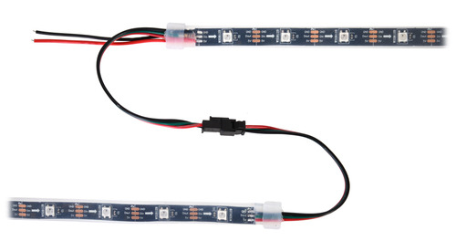 |
| Two WS2812B-based addressable RGB LED strips connected. |
|---|
We recommend 180 total RGB LEDs. It is fine to make longer chains with connected data lines, but you should power each 180-LED section separately. If you are powering a power supply, you have the power of the different power supply.
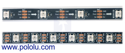
The LED strip is divided into segments, with each segment containing one RGB LED. The strip can be cut into the usable shorter sections. The data connection is labeled DO , Dout , DI , or Din , the positive power connection is labeled 5V , and the ground connection is labeled GND . Each LED in the picture is in the center of its own segment; there are little scissors drawn on the pcb silkscreen where the segments can be cut.
 |
These LED strips are controlled by a simple, high-speed one-wire protocol on the input signal line. The protocol is documented in the WS2812B datasheet (266k pdf) and also below.
The default, idle state of the signal line is low. To update the LED colors, you need to transmit a series of high pulses on the signal line. Each high pulse encodes one bit: a short pulse (0.35 μs) represents a zero, while a long pulse (0.9 μs) represents a one. The time between consecutive rising edges should be 1.25 μs (though in our tests, the strips worked with the cycle times up to approximately 6 μs). After the bits are sent, the signal line should be held for 50 μs to send a reset command. The pulse widths do not have to be precise if there is a threshold for work.
 |
| WS2812B RGB data timing diagram. |
|---|
The color of each LED is encoded as three LED brightness values, which must be sent in GRB (green-red-blue) order. Each brightness value is encoded as a series of 8 bits, with the most important bit being transmitted. LED color takes 24 bits. The first color is the LED input. The LED is in the strip, and so on.
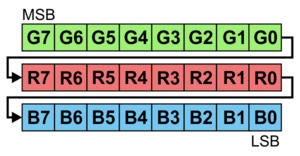 |
| 24 bits represent the color of one WS2812B LED in an addressable WS2812B RGB LED strip. |
|---|
To update all the LEDs in the strip, you should send all the colors at once with no pauses. If you send fewer colors than the number of LEDs on the strip, then some LEDs near the end of the strip will not be updated. For example, to update all 30 LEDs on a 1-meter strip, you would send 720 bits, encoded as high pulses and then hold the signal line for 50 μs. If multiple strips are chained together with the same line (two chained 1-meter strips behave the same as one 2-meter strip).
Each RGB LED receives data on line using the data output line. The high-speed protocol of the WS2812B allows for fast updates; our library for the Arduino is about 1.1 ms to update 30 LEDs, so it is possible to update 450 LEDs faster than 60 Hz. However, constant updates are not necessary; the LED strip can hold its state indefinitely as long as power reserves connected.
Since this LED strip does not use a standard protocol, and the software has a microcontroller. Because of the sub-microsecond timing, the bit-banging code needs to be printed. If it is interrupted in your code are fast enough,
Note: The minimum logic for the strip is 3.5 V, so you should use level-shifters if you want to control these strips from 3.3 V systems. In our tests, we were able to control them with. I could lead to unexpected problems.
To help you get started quickly, we provide sample code for these microcontroller platforms:
Cuk, the Adafruit NeoPixel library for Arduino should work with these strips since the NeoPixels are based on the WS2812B.
These WS2812B-based strips are similar to our older high-speed TM1804 LED strips (items # 2543, # 2544, and # 2545). The WS2812B's timing parameters are very fast. TM1804 LED strips, so you can use the same code to control them. However, the two types of strips have different, incompatible connectors, and the order of TM1804 colors are sent in the red-green-blue order while the WS2812B colors are sent in green-red -blue order.
The TM1804 is just an LED driver and it requires a separate RGB LED to be placed on the strip. Since the WS2812B combines the LED and the driver in a single package, it can be packed with more than 60 LEDs per meter.
Unlike the TM1804 strips, these LED strips do not have an adhesive backing, but they do include brackets as described above.
Manufacturer BTC Korporacja sp. z o. o. Lwowska 5 05-120 Legionowo Poland sprzedaz@kamami.pl 22 767 36 20
Responsible person BTC Korporacja sp. z o. o. Lwowska 5 05-120 Legionowo Poland sprzedaz@kamami.pl 22 767 36 20
Once again, Ugears returns to everybody’s favourite classics and introduces an exquisitely elegant and vigorously fast Roadster VM-01 sports car.
Your adventure begins when you open the box with your new model kit from Ugears. This is when you will experience the pleasant smell of natural wood that will stay with you all the way through the process of assembly, testing and play. Building the model is fascinating and exciting: with your own hands you will put plywood details together to create a 3-dimensional moving mechanical marvel. UGears 70052
No product available!
If you\'re like us at Ugears, you\'ve been spending a lot of time indoors lately. Is life getting a bit too predictable, too routine? Do you miss traveling? Is the open road calling your name? Have you ever dreamed of the freedom of two wheels? Time to turn your computer off and pull your leather jacket on! But wait...before you drop ten grand in the showroom at your local motorcycle dealer on that Triumph or Harley-Davidson you\'ve always dreamed of, may we suggest you first take a test drive with the Bike VM-02 3D wooden puzzle from Ugears? UGears 70051
No product available!
The Flexi-Cubus is a mechanical model, an octasphere puzzle in the form of a steampunk skeleton cube made out of eight joint-connected spheres. This flexible connection allows the spheres to move and roll over one another creating different geometrical shapes. UGears 70049
No product available!
UGEARS presents a new unique item for your collection of wooden models – loaded with fun, aimed at positive emotions, the Wolf-01 mechanical handgun.
This new arrival to UGEARS latest range is not a plain wooden toy where functionality is limited to imaginary shooting by means of yelling “Bang-bang!” The Wolf-01 is a proper mechanical handgun that can make up to 5 shots per round. It has outstanding performance and technical specifications, including the most important – a huge load of safe and peaceful fun! UGears 70047
No product available!
Inspired by the art of Celtic and Scandinavian medieval craftsmen, as translated through intelligent 21st century engineering, Ugears is proud to introduce the Hurdy-Gurdy—the world’s first (as far as we know!) mechanical model for self-assembly that is also a musical instrument. This extraordinary mechanical model kit is truly one of the gems of our catalogue. This isn\'t just a toy, it\'s a full-fledged musical instrument that you build yourself. The Hurdy-Gurdy has a sound that\'s perfect for folk melodies or dancing, bringing medieval times into the present day. When you purchase the Hurdy-Gurdy you will experience a unique combination: the fun and challenge of building, the appreciation of outstanding engineering and design, and the joy of music. UGears 70030
No product available!
The true jewel of Ugears new collection of wooden models is an exquisite Mechanical Treasure Box for jewellery and notes. Mysterious and intriguing puzzle boxes, known in many cultures and especially popular in Victorian England, could not pass by our attention. Beautiful recognizable Ugears design and traditional step-by-step puzzle give you the Treasure Box – delight to the eye and food for brain.
The delicate through-carved work of its lid and sides invites you to gain a glimpse into the mystery that the moving gears conceal. Although only the one who can solve the secrets of the puzzle-box will get to enjoy the treasure of beautiful mechanics in its action. UGears 70031
No product available!
Fanciers of fine automobiles will absolutely fall in love with Ugears\' Dream Cabriolet VM-05 wooden car model. This 1950s throwback is a beautiful showpiece but what really sets it apart is the model comes loaded with a host of moving parts and realistic detail. The Dream Cabriolet is an absolute marvel of design, featuring: a hood that lifts to reveal a V8 engine with moving pistons; a trunk that lifts to reveal the winding knob; transmission lever on the steering column that puts the car into reverse, idle or drive gear; front and rear suspension; doors that open and seats that push forward to let passengers in the back; and functional window cranks and windshield wipers. UGears 70073
No product available!
The thrill of speed, roar of engines, wheel to wheel battles and shiny frames flashing before the eyes of wildly excited audience of the early car races – it’s all there, in UGEARS’ fascinating U-9 Grand Prix Car based on iconic designs of the Golden Age of the automobile industry at the beginning of the XX century. UGears 70044
No product available!
Fidget away your stress or anxiety by building these U-Fidget Creations! These 4 unique miniature models are perfect for grown-ups and kids alike. They are made entirely from wooden materials and require no glue, toothpicks, or tools to assemble. UGears 70041
No product available!
The unique set of 4 individual miniature models for self-assembly for grown-ups and kids from 5 years to 80 and beyond. The set includes Sailing yacht, Sailboat, Boat, Submarine with basic elements of mechanics. UGears 70035
No product available!
The unique set of 4 individual miniature models for self-assembly for grown-ups and kids from 5 years to 80 and beyond. The set includes Sports Car, Tractor, Truck, TramCar with basic elements of mechanics. UGears 70033
No product available!
Do you fly in your dreams? Do you like the feeling? Once again Ugears makes the dream come true reaching out to the sky with its first ever aircraft model represented by two flying machines in one package. Introducing – The Aviator model.
The model has three modules: the airplane, the helicopter and the flight control tower. Choose between your aircraft, set one on the tower’s bar and you are good to fly. As a beginner pilot you might want to start with the helicopter which is not as difficult to control as the airplane. Easier to manipulate but no less exciting, your chopper has a cockpit with doors that open and shut, and three-blade main and tail rotors. UGears 70053
No product available!
The Tower Windmill from Ugears is more than a mechanical puzzle. It is an exciting adventure into the history of old England. The model is based on the Chesterton Windmill, a 17th-century cylindrical stone tower windmill that was built outside the village of Chesterton, Warwickshire county. Built around 1632-33, the Windmill was restored between 1965 and 1974 and today it is the earliest tower mill in England to retain any of its working parts.
This unique construction with an arched base was presumably built by a prominent figure of the period, Sir Edward Peyto that owned Chesterton Manor at that time. UGears 70055
No product available!
Pick a card, any card — or a whole pack! The UGears Games Card Holder stores up to 12 decks of playing cards, allowing easy access while saving space on your game table. No more rummaging through boxes or stacks on shelves to find the stack of cards you need. UGears 70068
No product available!
The V-Ekspres tender locomotive from UGEARS is a model that offers both an aesthetic experience and educational value, making it an ideal choice for lovers of mechanics, history and travel. UGears 70058
No product available!
Before the Age of Steam took over the world, drastically changing every sphere of human activity, the only reliable transport available to travellers had been strong and fast horses. Ugears looks away from high end technologies and ultrahigh-speed to appreciate the time of travelling by horse-back with a model joining nature and mechanics – the Bionic Horse. UGears 70054
No product available!

Addressable RGB 120-LED Strip, 5V, 2m (WS2812B)
