


zł838.94 tax excl.
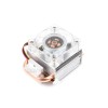
Standard 20-pin 0.1 male connector to provide electrical isolation, Segger
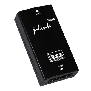
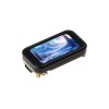
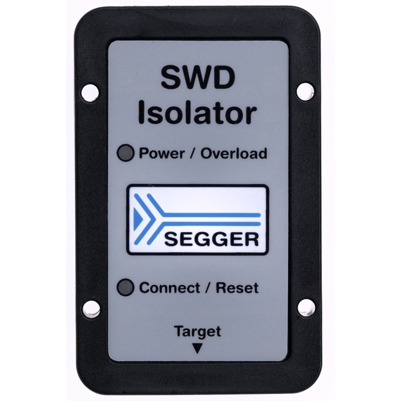
J-Link SWD Isolator (8.07.01)
The J-Link SWD Isolator can be connected between J-Link and any ARM-board that uses the standard 20-pin 0.1" male connector to provide electrical isolation. This is essential when the development tools are not connected to the same ground as the application. It is also useful to protect the development tools from electrical spikes that often occur in some applications, such as motor control applications. Another typical field of application is development of products with sensors or other analog circuitry, in which case the target hardware is protected from electrical noise originating from the development PC.
The J-Link SWD Isolator is compatible with J-Link, J-Link Pro, J-Link Ultra, J-Link Ultra+ and Flasher ARM.
Features
Power supply
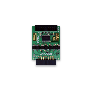
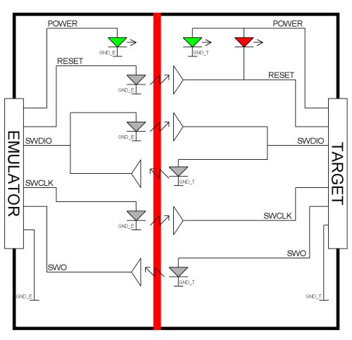
Both sides, target and emulator, are totally isolated from each other and separately powered. The target side draws power from pins 1 or 2, the emulator side draws power from pin 19.
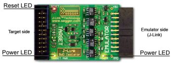
Connectors and indicators
The SWD Isolator uses high speed optocouplers that allow a very low propagation time between input and output. It comes with the following connectors and indicators:
Block diagram
The following functional block diagram illustrates the functional connections between the emulator and target.
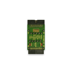
Target connector
The following picture shows the target side pinout of the J-Link SWD Isolator:
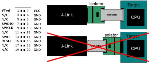
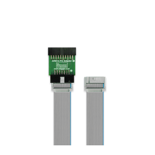
The Emulator side of the Isolator is plugged directly into the Emulator. The Target side is connected to the target via a 20-pin flat cable.
Download:
Code: J-Link SWD Isolator (8.07.01)
Manufacturer BTC Korporacja sp. z o. o. Lwowska 5 05-120 Legionowo Poland sprzedaz@kamami.pl 22 767 36 20
Responsible person BTC Korporacja sp. z o. o. Lwowska 5 05-120 Legionowo Poland sprzedaz@kamami.pl 22 767 36 20
JTAG interface galvanic separator that protects equipment against damage caused by potential differences, with a maximum clock frequency of 110 MHz, 3-5 V power supply, and isolation voltage up to 1 kVDC, equipped with multiple connectors and optical status signaling
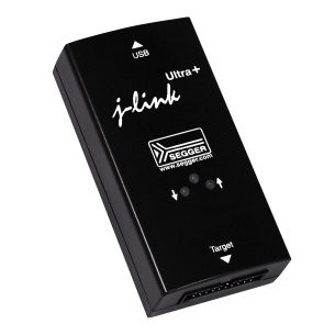
Hi-Speed JTAG/SWD Emulator for ARM7/9, Cortex and Renesas RX cores with USB interface, Segger
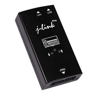
Hi-Speed JTAG/SWD Emulator with USB and Ethernet interface, Segger
No product available!
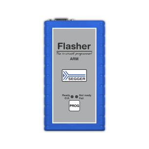
Flash Programmer for ARM and Cortex cores, Segger
A set of three adapters for SO-8, SO-8W and SO-16 memories that allows easy testing and programming of flash devices in these packages, eliminating the need for dedicated solutions for each form factor. The adapters are compatible with the SEGGER (Q)SPI Flash Evaluator and other test systems, making them a versatile tool for both test and production. SEGGER (Q)SPI Flash Evaluator Adapter Board Pack for SO-8, SO-8W, SO-16 (6.40.01)
No product available!
J-Link ARM-14 Adapter, RoHS
Standard 20-pin 0.1 male connector to provide electrical isolation, Segger
A module that enables precise switching of Flasher signals in production environments, preventing interference between test devices connected to the same lines. By controlling relays via VTSUPPLY, it ensures stable and reliable operation in testing and programming processes. Segger Relay Adapter (8.06.41)
No product available!
The Segger J-Link Measurement+Patch Adapter allows you to easily customize connections between J-Link or Flasher devices and boards that do not have a standard debug connector. It is equipped with colored wires for signal identification, test points and jumpers for adjusting the voltages on the pins.
No product available!
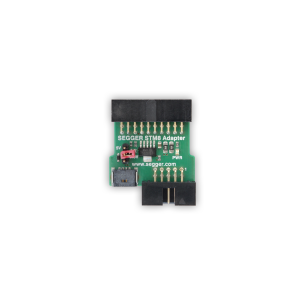
Adapter that converts standard 20-pin 2.54 mm connector to SWIM connector and 10-pin connector. Used for programming STM8 chips. Segger STM8 Adapter (8.06.22)
No product available!
A specialized demonstration board designed to support Tail Tagging within the embOS/IP IP stack. Using this technology, it is possible to transform a single Ethernet port into several logical ports, enabling the creation of a virtual multiport network using only a single Ethernet port. Segger embOS/IP Switch Board (6.70.00)
No product available!
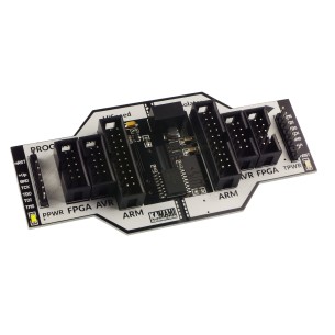
The Intel FPGA Adapter (formerly J-Link Altera Adapter) connects to the Intel FPGA 10-pin JTAG connector, enabling debugging of FPGA-based MCU cores such as the dual-core Arm Cortex-A9 in Cyclone V devices. on Intel FPGA solutions.
No product available!
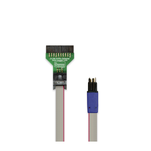
J-Link 6-pin Needle Adapter (8.06.16)
Adapter enabling easy connection of a Microchip AVR microcontroller device with the SEGGER Flasher programming system, supporting 6-pin and 10-pin connectors and providing fast connection via SPI protocol. With the function of powering the target hardware (3.3V or 5V) and direct power supply via VTREF connection, the adapter is flexible, easy to use and ideal for programming and debugging AVR microcontrollers in embedded systems, providing reliable communication and high precision. Segger AVR SPI Adapter (8.06.25)
No product available!
J-Link 19-pin Cortex-M Adapter, RoHS, Segger
Adapter enabling connection of Flasher PRO programmers and other Flasher models to devices with a 10-pin Renesas connector. It is compatible with M16C, M32C, R8C and R32C microcontrollers, providing stable communication and easy integration with older and modern programming systems. Segger Renesas M16C Family 10-Pin Adapter (8.06.40)
No product available!
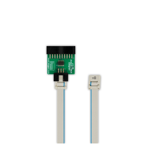
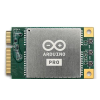
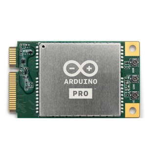
Segger Arduino MKR adapter (8.06.37) with 6-pin 0.05" and 20-pin JTAG connectors, designed for connecting Segger programmers and debuggers, enables efficient programming and testing of Arduino MKR boards.
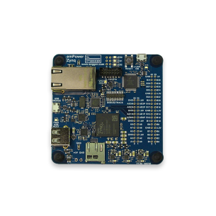
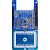
Advanced evaluation board designed for rapid implementation of embedded solutions. Supporting the embOS operating system and SEGGER tools such as emFile, emWin, emUSB and emNet, the board is an ideal platform for software testing and application development in an environment based on the Xilinx Zynq XC7Z007S SoC with ARM Cortex-A9 processor and Artix7 FPGA. Segger emPower Zynq (6.31.00)
No product available!
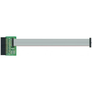
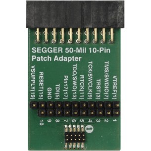
Adapter from the standard 20-pin 2.54 mm connector to the 10-pin 1.27 mm connector often used in Cortex-M boards. Segger 50-Mil 10-Pin Patch Adapter (8.06.28)
No product available!
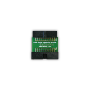
The Segger J-Link Signal Smoothing Adapter (8/06/12) is designed to improve signal integrity between the J-Link debug probe and the target debug device. It allows JTAG signals to be suppressed by adjustable series resistors, preventing excessive gain and jitter.
No product available!
Standard 20-pin 0.1 male connector to provide electrical isolation, Segger