


zł31.07 tax excl.
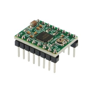
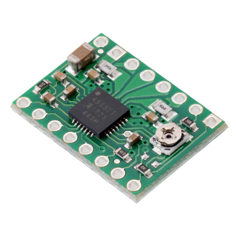
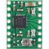
A4988 Stepper Motor Driver Carrier
A4988 Stepper Motor Driver Carrier
The A4988 stepper motor driver carrier is a breakout board for Allegro’s easy-to-use A4988 microstepping bipolar stepper motor driver and is a drop-in replacement for the A4983 stepper motor driver carrier. The driver features adjustable current limiting, overcurrent protection, and five different microstep resolutions. It operates from 8 – 35 V and can deliver up to 2 A per coil.
Limited stock until mid-August: We are limiting immediate shipments to five (5) units per order until our supply of these units improves. Orders for larger quantities will be accepted but put on backorder.
Limited stock until mid-August: We are limiting immediate shipments to five (5) units per order until our supply of these units improves. Orders for larger quantities will be accepted but put on backorder.
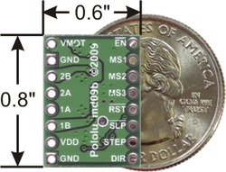 |
| A4983/A4988 stepper motor driver carrier with dimensions. |
|---|
This product is a carrier board or breakout board for Allegro’s A4988 DMOS Microstepping Driver with Translator and Overcurrent Protection; we therefore recommend careful reading of the A4988 datasheet (380k pdf) before using this product. This stepper motor driver lets you control one bipolar stepper motor at up to 2 A output current per coil (see the Power Dissipation Considerations section below for more information). Here are some of the driver’s key features:
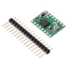
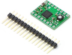
Like nearly all our other carrier boards, this product ships with all surface-mount components—including the A4988 driver IC—installed as shown in the product picture.
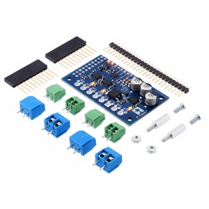
We also sell a larger version of the A4988 carrier that has reverse power protection on the main power input and built-in 5 V and 3.3 V voltage regulators that eliminate the need for separate logic and motor supplies.
Some unipolar stepper motors (e.g. those with six or eight leads) can be controlled by this driver as bipolar stepper motors. For more information, please see the frequently asked questions. Unipolar motors with five leads cannot be used with this driver.
The A4988 stepper motor driver carrier comes with one 1?16-pin breakaway 0.1" male header. The headers can be soldered in for use with solderless breadboards or 0.1" female connectors. You can also solder your motor leads and other connections directly to the board.
 |
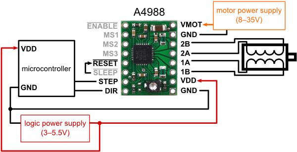 |
| Minimal wiring diagram for connecting a microcontroller to an A4988 stepper motor driver carrier (full-step mode). |
|---|
The driver requires a logic supply voltage (3 – 5.5 V) to be connected across the VDD and GND pins and a motor supply voltage of (8 – 35 V) to be connected across VMOT and GND. These supplies should have appropriate decoupling capacitors close to the board, and they should be capable of delivering the expected currents (peaks up to 4 A for the motor supply).
Warning: This carrier board uses low-ESR ceramic capacitors, which makes it susceptible to destructive LC voltage spikes, especially when using power leads longer than a few inches. Under the right conditions, these spikes can exceed the 35 V maximum voltage rating for the A4988 and permanently damage the board, even when the motor supply voltage is as low as 12 V. One way to protect the driver from such spikes is to put a large (> 50 µF) electrolytic capacitor across motor power (VMOT) and ground somewhere close to the board.
Four, six, and eight-wire stepper motors can be driven by the A4988 if they are properly connected; a FAQ answer explains the proper wirings in detail.
Warning: Connecting or disconnecting a stepper motor while the driver is powered can destroy the driver. (More generally, rewiring anything while it is powered is asking for trouble.)
Stepper motors typically have a step size specification (e.g. 1.8° or 200 steps per revolution), which applies to full steps. A microstepping driver such as the A4988 allows higher resolutions by allowing intermediate step locations, which are achieved by energizing the coils with intermediate current levels. For instance, driving a motor in quarter-step mode will give the 200-step-per-revolution motor 800 microsteps per revolution by using four different current levels.
The resolution (step size) selector inputs (MS1, MS2, MS3) enable selection from the five step resolutions according to the table below. MS1 and MS3 have internal 100kΩ pull-down resistors and MS2 has an internal 50kΩ pull-down resistor, so leaving these three microstep selection pins disconnected results in full-step mode. For the microstep modes to function correctly, the current limit must be set low enough (see below) so that current limiting gets engaged. Otherwise, the intermediate current levels will not be correctly maintained, and the motor will effectively operate in a full-step mode.
| MS1 | MS2 | MS3 | Microstep Resolution |
|---|---|---|---|
| Low | Low | Low | Full step |
| High | Low | Low | Half step |
| Low | High | Low | Quarter step |
| High | High | Low | Eighth step |
| High | High | High | Sixteenth step |
Each pulse to the STEP input corresponds to one microstep of the stepper motor in the direction selected by the DIR pin. Note that the STEP and DIR pins are not pulled to any particular voltage internally, so you should not leave either of these pins floating in your application. If you just want rotation in a single direction, you can tie DIR directly to VCC or GND. The chip has three different inputs for controlling its many power states: RST, SLP, and EN. For details about these power states, see the datasheet. Please note that the RST pin is floating; if you are not using the pin, you can connect it to the adjacent SLP pin on the PCB.
To achieve high step rates, the motor supply is typically much higher than would be permissible without active current limiting. For instance, a typical stepper motor might have a maximum current rating of 1 A with a 5Ω coil resistance, which would indicate a maximum motor supply of 5 V. Using such a motor with 12 V would allow higher step rates, but the current must actively be limited to under 1 A to prevent damage to the motor.
The A4988 supports such active current limiting, and the trimmer potentiometer on the board can be used to set the current limit. One way to set the current limit is to put the driver into full-step mode and to measure the current running through a single motor coil without clocking the STEP input. The measured current will be 0.7 times the current limit (since both coils are always on and limited to 70% in full-step mode). Please note that the current limit is dependent on the Vdd voltage.
Another way to set the current limit is to measure the voltage on the “ref” pin and to calculate the resulting current limit (the current sense resistors are 0.05Ω). The ref pin voltage is accessible on a via that is circled on the bottom silkscreen of the circuit board. See the A4988 datasheet for more information.
The A4988 driver IC has a maximum current rating of 2 A per coil, but the actual current you can deliver depends on how well you can keep the IC cool. The carrier’s printed circuit board is designed to draw heat out of the IC, but to supply more than approximately 1 A per coil, a heat sink or other cooling method is required.
This product can get hot enough to burn you long before the chip overheats. Take care when handling this product and other components connected to it.
Please note that measuring the current draw at the power supply does not necessarily provide an accurate measure of the coil current. Since the input voltage to the driver can be significantly higher than the coil voltage, the measured current on the power supply can be quite a bit lower than the coil current (the driver and coil basically act like a switching step-down power supply). Also, if the supply voltage is very high compared to what the motor needs to achieve the set current, the duty cycle will be very low, which also leads to significant differences between average and RMS currents.
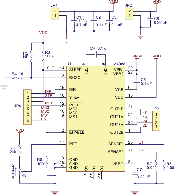 |
| Schematic diagram of the md09b A4988 stepper motor driver carrier. |
|---|
Note: This board is a drop-in replacement for our original A4983 stepper motor driver carrier. The newer A4988 offers overcurrent protection and has an internal 100k pull-down on the MS1 microstep selection pin, but it is otherwise virtually identical to the A4983.
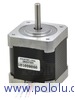 |
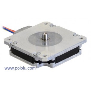
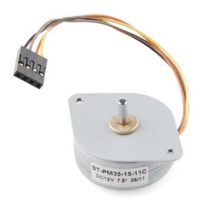
Stepper Motor: Unipolar/Bipolar, 200 Steps/Rev, 42x48mm, 4V, 1200mA |
Data sheet
Manufacturer BTC Korporacja sp. z o. o. Lwowska 5 05-120 Legionowo Poland sprzedaz@kamami.pl 22 767 36 20
Responsible person BTC Korporacja sp. z o. o. Lwowska 5 05-120 Legionowo Poland sprzedaz@kamami.pl 22 767 36 20
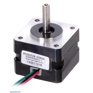
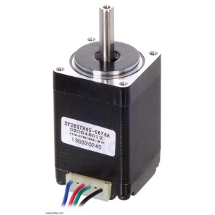
Bipolar stepper motor. It has a resolution of 200 steps/revolution (1.8 ° per step), has a nominal voltage of 7.4 V, and draws a current of 0.28 A per coil. Pololu 1207
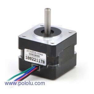
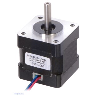
Bipolar stepper motor. It has a resolution of 200 steps/revolution (1.8° per step), a rated voltage of 10 V, and draws a current of 0.5 A per coil. Pololu 1208
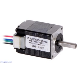
Bipolar stepper motor. It has a resolution of 200 steps/revolution (1.8° per step), a rated voltage of 3.9 V, and draws a current of 0.6 A per coil. Pololu 1204
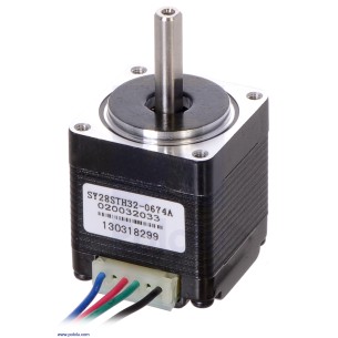
Bipolar stepper motor. It has a resolution of 200 steps/revolution (1.8° per step), rated voltage of 3.8 V, and has a current consumption of 0.67 A per coil. Pololu 1205
Bipolar stepper motor. It has a resolution of 200 steps/revolution (1.8° per step), a rated voltage of 4.5 V, and draws a current of 0.67 A per coil. Pololu 1206
No product available!
Bipolar stepper motor. It has a resolution of 200 steps/revolution (1.8 ° per step), a rated voltage of 2.7V, and draws a current of 1A per coil. Pololu 1209
No product available!
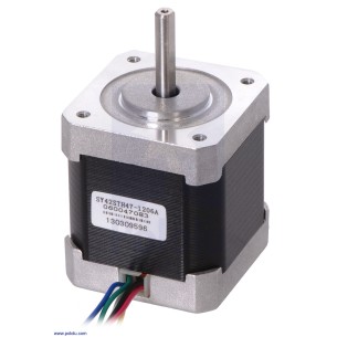
Bipolar stepper motor. It has a resolution of 200 steps/revolution (1.8° per step), has a nominal voltage of 4 V and draws a current of 1.2 A per coil. Pololu 1200
Bipolar stepper motor. It has a resolution of 200 steps/revolution (1.8° per step), a rated voltage of 4.5 V, and draws a current of 1 A per coil. Pololu 2297
No product available!
Bipolar stepper motor powered with a voltage of up to 12 V and a maximum current of 400 mA. SparkFun ROB-10551
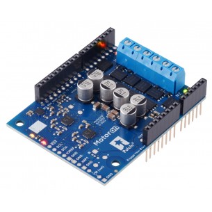
The stepper motor driver with Allegro A4988 (A4988 Stepper Motor Driver Carrier) allows you to supply a bipolar current of up to 2A per phase. The system can be supplied with voltage up to 35V, in the set there is a heat sink. It is compatible with Polol 1182
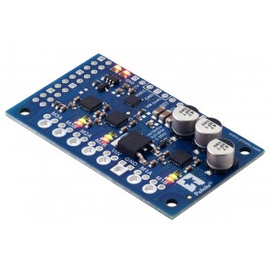
DC motor driver that allows you to control the movement of three drives using the I2C interface. Connectors for self-assembly. Pololu 5034
DC motor driver that allows you to control the movement of three drives using the I2C interface. Pololu 5035
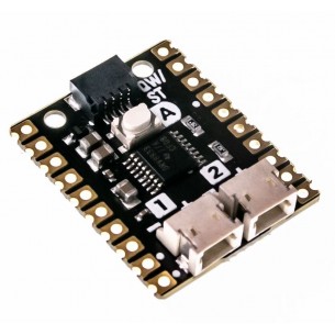
A module with a two-channel DC motor driver based on the TB6612FNG system. Designed for Wemos D1 Mini
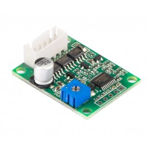
The bidirectional ESC controller enables precise control of brushed DC motors within a voltage range equivalent to 1S–2S Li-Ion/Li-Po packs. Its small size and compatibility with classic RC signals facilitate applications in compact mobile designs and robotic projects with limited mounting space
No product available!
The ESC RC controller module is designed for brush motors with a supply voltage from 3.5 to 6 V and a capacity of 1 A
ESC RC controller module with FlySky receiver designed for two brush motors with a supply voltage from 2.5 to 5 V and a current consumption of 2 A
No product available!
Brushless DC motor (BLDC) driver. It can operate motors powered with a voltage from 6 to 20 V with a current consumption of up to 3 A
Module with 2-channel DC motor driver DRV8833 designed to work with the Raspberry Pi Pico. It can work with a voltage from 2.7 to 10.8 V and a current of up to 1.2 A. Pimoroni PIM617
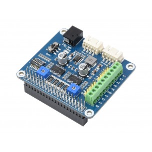
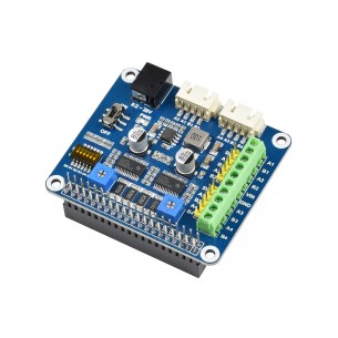
Extension module with a driver for two stepper motors based on the HR8825 system. Dedicated for Raspberry Pi minicomputers. Waveshare Stepper Motor HAT (B)
Extension module with a driver for two stepper motors based on the DRV8825 system. Dedicated for Raspberry Pi minicomputers. Waveshare Stepper Motor HAT
No product available!
DC motor driver that allows you to control the movement of two drives using the I2C interface. Board without connectors. Pololu 5047
No product available!
DC motor driver that allows you to control the movement of two drives using the I2C interface. Board with connectors for self-assembly. Pololu 5046
No product available!
DC motor driver that allows you to control the movement of two drives using the I2C interface. Board with soldered connectors. Pololu 5045
No product available!
DC motor driver that allows you to control the movement of two drives using the I2C interface. Board without connectors. Pololu 5044
No product available!
DC motor driver that allows you to control the movement of two drives using the I2C interface. Board with connectors for self-assembly. Pololu 5043
No product available!
DC motor driver that allows you to control the movement of two drives using the I2C interface. Board with soldered connectors. Pololu 5042
No product available!
A4988 Stepper Motor Driver Carrier