


zł242.70 tax excl.
Pololu High-Power Motor Driver 36v9
Pololu High-Power Motor Driver 36v9
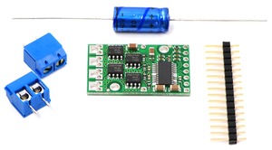
This discrete MOSFET H-bridge motor driver enables bidirectional control of one high-power DC brushed motor. The little 1.3×0.8-inch board supports a wide 5.5 to 50 V voltage range and is efficient enough to deliver a continuous 9 A without a heat sink.
 |
The Pololu high-power motor driver is a discrete MOSFET H-bridge designed to drive large DC brushed motors. The H-bridge is made up of one N-channel MOSFET per leg, and most of the board’s performance is determined by these MOSFETs (the rest of the board contains the circuitry to take user inputs and control the MOSFETs). The MOSFET datasheet is available under the “Resources” tab. The absolute maximum voltage for this motor driver is 50 V. Under normal operating conditions, ripple voltage on the supply line can raise the maximum voltage to more than the average or intended voltage, so a safe maximum voltage is approximately 44 V.
Note: Battery voltages can be much higher than nominal voltages when they are charged, so the maximum battery voltage we recommend is 36 V unless appropriate measures are taken to limit the peak voltage.
The versatility of this driver makes it suitable for a large range of currents and voltages: it can deliver up to 9 A of continuous current with a board size of only 1.3" by 0.8" and no required heat sink. With the addition of a heat sink, it can drive a motor with up to about 12 A of continuous current. The module offers a simple interface that requires as little as two I/O lines while allowing for both sign-magnitude and locked-antiphase operation. Integrated detection of various short-circuit conditions protects against common causes of catastrophic failure; however, please note that the board does not include reverse power protection or any over-current or over-temperature protection.
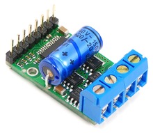
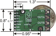
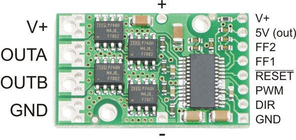
The motor and motor power connections are on one side of the board, and the control connections (5V logic) are on the other side. The motor supply should be capable of supplying high current, and a large capacitor should be installed close to the motor driver. The included axial capacitor can be installed directly on the board in the pins labeled '+' and '-' as shown below. Such installations are compact but might limit heat sinking options; also, depending on the power supply quality and motor characteristics, a larger capacitor might be required. There are two options for connecting to the high-power signals (V+, OUTA, OUTB, GND): large holes on 0.2" centers, which are compatible with the included terminal blocks, and pairs of 0.1"-spaced holes that can be used with perfboards, breadboards, and 0.1" connectors.
Warning: Take proper safety precautions when using high-power electronics. Make sure you know what you are doing when using high voltages or currents! During normal operation, this product can get hot enough to burn you. Take care when handling this product or other components connected to it.
The logic connections are designed to interface with 5V systems (5.5 V max); the minimum high input signal threshold is 3.5 V, so we do not recommend connecting this device directly to a 3.3 V controller. In a typical configuration, only PWM and DIR are required. The two fault flag pins (FF1 and FF2) can be monitored to detect problems (see the Fault Flag Table below for more details). The RESET pin, when held low, puts the driver into a low-power sleep mode and clears any latched fault flags. The V+ pin on the logic side of the board gives you access to monitor the motor’s power supply (it should not be used for high current). The board also provides a regulated 5 V pin which can provide a few milliamps (this is typically insufficient for a whole control circuit but can be useful as a reference or for very low-power microcontrollers).
 |
| PIN | Default State | Description |
|---|---|---|
| V+ | This is the main 5.5 – 30 V motor power supply connection, which should typically be made to the larger V+ pad. The smaller V+ pad along the long side of the board is intended for a power supply capacitor, and the smaller V+ pad on the logic side of the board gives you access to monitor the motor’s power supply (it should not be used for high current). | |
| 5V (out) | This regulated 5V output provides a few milliamps. This output should not be connected to other external power supply lines. Be careful not to accidentally short this pin to the neighboring V+ pin while power is being supplied as doing so will instantly destroy the board! | |
| GND | Ground connection for logic and motor power supplies. | |
| OUTA | A motor output pin. | |
| OUTB | B motor output pin. | |
| PWM | LOW | Pulse width modulation input: a PWM signal on this pin corresponds to a PWM output on the motor outputs. |
| DIR | FLOAT | Direction input: when DIR is high current will flow from OUTA to OUTB, when it is low current will flow from OUTB to OUTA. |
| RESET | HIGH | The reset pin, when pulled low, puts the board into a low-power sleep mode and clears any latched fault flags. |
| FF1 | LOW | Fault flag 1 indicator: FF1 goes high when certain faults have occurred. See table below for details. |
| FF2 | LOW | Fault flag 2 indicator: FF2 goes high when certain faults have occurred. See table below for details. |
A 16-pin straight breakaway male header, one 100 uF capacitor, and two 2-pin 5mm terminal blocks are included with each motor driver. Connecting a large capacitor across the power supply is recommended; one way to do it is between the '+' and '-' holes, as shown below. The two mounting holes are intended to be used with #2 screws (not included).
|
|
With the PWM pin held low, both motor outputs will be held low (a brake operation). With PWM high, the motor outputs will be driven according to the DIR input. This allows two modes of operation: sign-magnitude, in which the PWM duty cycle controls the speed of the motor and DIR controls the direction, and locked-antiphase, in which a pulse-width-modulated signal is applied to the DIR pin with PWM held high.
In locked-antiphase operation, a low duty cycle drives the motor in one direction, and a high duty cycle drives the motor in the other direction; a 50% duty cycle turns the motor off. A successful locked-antiphase implementation depends on the motor inductance and switching frequency smoothing out the current (e.g. making the current zero in the 50% duty cycle case), so a high PWM frequency might be required.
| Motor Driver Truth Table | ||||
|---|---|---|---|---|
| PWM | DIR | OUTA | OUTB | Operation |
| H | L | L | H | Forward |
| H | H | H | L | Backward |
| L | X | L | L | Brake |
The motor driver supports PWM frequencies as high as 40 kHz, though higher frequencies result in higher switching losses in the motor driver. Also, the driver has a dead time (when the outputs are not driven) of approximately 3 us per cycle, so high duty cycles become unavailable at high frequencies. For example, at 40 kHz, the period is 25 us; if 3 us of that is taken up by the dead time, the maximum available duty cycle is 22/25, or 88%. (100% is always available, so gradually ramping the PWM input from 0 to 100% will result in the output ramping from 0 to 88%, staying at 88% for inputs of 88% through 99%, and then switching to 100%.)
The motor driver can handle large current spikes for short durations (e.g. 100 A for a few milliseconds). The peak ratings are for quick transients (e.g. when a motor is first turned on), and the continuous rating of 9 A is dependent on various conditions, such as the ambient temperature. The actual current you can deliver will depend on how well you can keep the motor driver cool. The driver’s printed circuit board is designed to draw heat out of the MOSFETs, but performance can be improved by adding a heat sink. With a heat sink the motor driver can be run at up to 12 A of continuous current. For more information on power dissipation see the data sheet for the MOSFETs on the Resources tab.
Warning: This motor driver has no over-current or over-temperature shut-off. Either condition can cause permanent damage to the motor driver. You might consider using an external current sensor, such as our ACS714 ±30A bidirectional current sensor carrier to monitor your current draw.
The motor driver can detect three different fault states, which are reported on the FF1 and FF2 pins. The detectable faults are short circuits on the output, under-voltage, and over-temperature. A short-circuit fault is latched, meaning the outputs will stay off and the fault flag will stay high, until the board is reset (RESET brought low). The under-voltage fault disables outputs but is not latched. The over-temperature fault provides a weak indication of the board being too hot, but it does not directly indicate the temperature of the MOSFETs, which are usually the first components to overheat. The fault flag operation is summarized below.
| Flag State | Fault Description | Disable Outputs | Latched Until Reset | |
|---|---|---|---|---|
| FF1 | FF2 | |||
| L | L | No fault | No | No |
| L | H | Short Circuit | Yes | Yes |
| H | L | Over Temperature | No | No |
| H | H | Under Voltage | Yes | No |
There are currently nine versions of the high-power motor driver. The three CS versions have the same pinout, and the six non-CS versions have the same pinout. The following table provides a comparison of the high-power motor drivers:
| Pololu high-power motor drivers | ||
|---|---|---|
| Name | Max nominal battery voltage (V) | Max continuous current (A) w/o heat sink |
| High-power motor driver 18v25 CS | 18 | 25 |
| High-power motor driver 18v25 | 18 | 25 |
| High-power motor driver 18v15 | 18 | 15 |
| High-power motor driver 24v23 CS | 28 | 23 |
| High-power motor driver 24v20 | 28 | 20 |
| High-power motor driver 24v12 | 28 | 12 |
| High-power motor driver 36v20 CS | 36 | 20 |
| High-power motor driver 36v15 | 36 | 15 |
| High-power motor driver 36v9 | 36 | 9 |
Note: Please consider our Simple Motor Controllers as alternatives to these motor drivers. They have very similar power characteristics and offer high-level interfaces (e.g. USB, RC hobby servo pulses, analog voltages, and TTL serial commands) that make them much easier to use for many applications.
 |
ACS714 Current Sensor Carrier -5 to +5A |
Data sheet
Manufacturer BTC Korporacja sp. z o. o. Lwowska 5 05-120 Legionowo Poland sprzedaz@kamami.pl 22 767 36 20
Responsible person BTC Korporacja sp. z o. o. Lwowska 5 05-120 Legionowo Poland sprzedaz@kamami.pl 22 767 36 20
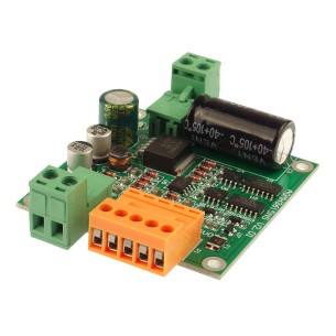
Single-channel DC motor driver that can control the movement of the drive with a supply voltage of up to 36 V and a current consumption of up to 15 A. Controlled by a PWM signal. DFRobot DRI0042
Ultra small Dual DC motor driver for some room limited projects. UVLO (Under Voltage Latch-Out) features a safe guard for your system. DRI0041
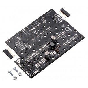
The power module together with the engine controller has been specially created for the Romi Chassis chassis. With its help, we will supply all components of our construction and we will be able to control the engines responsible for the movement of the chassis. Pololu 3543
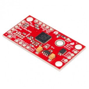
Two-channel DC motor driver communicating via UART, SPI or I2C interface. It can control the movement of 3 to 11V motors with a maximum continuous current of 1.2A per channel. SparkFun ROB-13911
No product available!
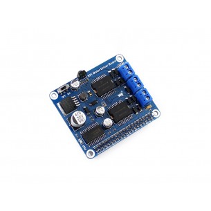
Raspberry Pi Expansion Board, DC Motor / Stepper Motor Driver
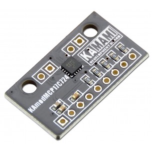
KAmodMPC17C724 is a module with a double MP bridge bridge type MPC17C724. The system allows you to control two DC brush motors or one bipolar stepping motor. The controller operates at a voltage range of 2.7 - 5.5 V and can work with motors with power consumption up to 0.4 A.
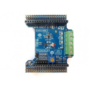
The X-NUCLEO-IHM11M1 is a low voltage three-phase brushless DC motor driver expansion board based on the STSPIN230 for STM32 Nucleo. It provides an affordable and easy-to-use solution for the implementation of portable motor driving applications such as thermal printers, robotics and toys
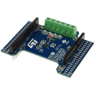
The X-NUCLEO-IHM12A1 is a low voltage dual brush DC motor driver expansion board based on the STSPIN240 for STM32 Nucleo. It provides an affordable and easy-to-use solution for the implementation of portable motor driving applications such as thermal printers, robotics and toys
No product available!
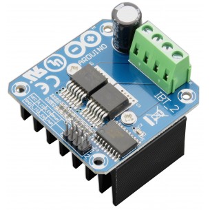
The high power motor driver module works on the basis of Infineon BTS7960B systems. Maximum controller current: 43 A, operating voltage range: 5.5V - 27V. The module has a heat sink and can be controlled from the Arduino, Raspberry Pi, and STM levels. IBT_2
No product available!
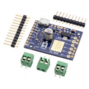
The Tic T825 USB Multi-Interface Stepper Motor Controller makes basic control of a stepper motor easy, with quick configuration over USB using our free software. The controller supports six control interfaces: USB, TTL serial, I²C, analog voltage (potentiometer), quadrature encoder, and hobby radio control (RC).
The Tic T825 USB Multi-Interface Stepper Motor Controller makes basic control of a stepper motor easy, with quick configuration over USB using our free software. The controller supports six control interfaces: USB, TTL serial, I²C, analog voltage (potentiometer), quadrature encoder, and hobby radio control (RC).
No product available!
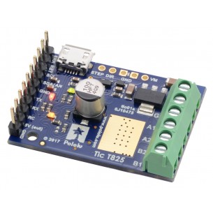
Stepper motor driver based on TB67S249FTG. It allows you to control a stepper motor with voltage from 10 to 47V, with a maximum current of 1.8A. The controller can be controlled using: USB, Serial TTL, I2C, RC (PWM modeling), analog input or quadrature encoder. Pololu 3138
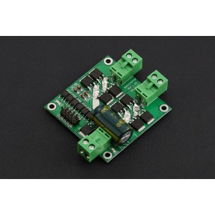
Powerful DC motor driver. It allows you to control a motor with a power supply voltage in the range of 6 ... 28 V, the motor can draw current of 100 A (using a heat sink). For the control PWM modeling (eg from RC receivers) is used in robotics, small electric vehicles or wherever there is a need to control a DC motor. Digilent 410-334-1
No product available!
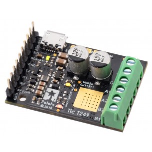
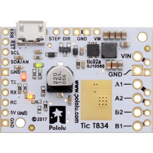
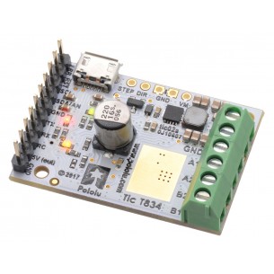
The Tic T834 USB Multi-Interface Stepper Motor Controller makes basic control of a stepper motor easy, with quick configuration over USB using our free software. The controller supports six control interfaces: USB, TTL serial, I²C, analog voltage (potentiometer), quadrature encoder, and hobby radio control (RC).
The Tic T834 USB Multi-Interface Stepper Motor Controller makes basic control of a stepper motor easy, with quick configuration over USB using our free software. The controller supports six control interfaces: USB, TTL serial, I²C, analog voltage (potentiometer), quadrature encoder, and hobby radio control (RC).
No product available!
Pololu High-Power Motor Driver 36v9