


zł109.88 tax excl.
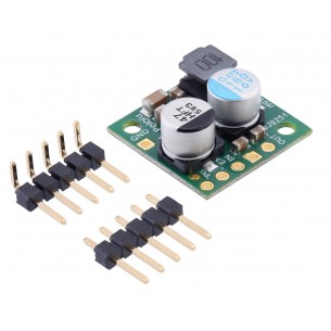
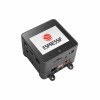
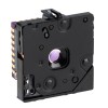
Pololu 12V Step-Up Voltage Regulator U3V50F12
Pololu 12V Step-Up Voltage Regulator U3V50F12
This powerful boost regulator efficiently generates an output voltage of 12 V from an input voltage as low as 2.9 V while allowing an input current as high as 5 A.
 |
These boost (step-up) voltage regulators generate higher output voltages from input voltages as low as 2.9 V. They are switching regulators (also called switched-mode power supplies (SMPS) or DC-to-DC converters) and have a typical efficiency between 80% to 95%. The available output current is a function of the input voltage, output voltage, and efficiency (see Typical Efficiency and Output Current section below), but the input current can typically be as high as 5 A. This regulator is available with a fixed 5 V, 6 V, 9 V, 12 V, or 24 V output:
The U3V50x regulator family also includes two adjustable-output versions: the U3V50ALV offers an output range of 4 V to 12 V and the U3V50AHV offers an output range of 9 V to 30 V. The different versions of the board all look very similar, so the bottom silkscreen includes a blank space where you can add your own distinguishing marks or labels.
The no-load quiescent current depends on the difference between the input and the output voltage. When the two are close, the quiescent current can be less then a milliamp (e.g. 0.6 mA with 5 V in and 6 V out); when the two are far apart, it might be in the tens of milliamps (e.g. 24 mA with 3 V in and 24 V out).
This regulator has built-in reverse-voltage protection, over-current protection, thermal shutdown (which typically activates at 165°C), and an under-voltage lockout that causes the regulator to turn off when the input voltage is below 2.5 V (typical).
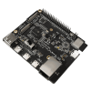
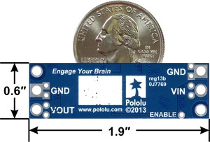
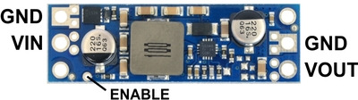
The boost regulator has four connections: input voltage (VIN), ground (GND), and output voltage (VOUT), and ENABLE.
 |
The input voltage, VIN, must be at least 2.9 V and should not exceed the output voltage, VOUT. (If VIN is higher than VOUT, the higher input voltage will show up on the output, which is potentially dangerous for your connected load and could also damage the regulator.)
The ENABLE pin can be driven low (under 0.7 V for at least 1 ms) to put the board into a low-power state. The quiescent current draw in this sleep mode is dominated by the current in the 100kO pull-up resistor from ENABLE to VIN and by the reverse-voltage protection circuit, which will draw approximately 20 µA per volt on VIN when ENABLE is held low. The ENABLE pin can be driven high (above 1.3 V to enable the board, or it can be connected to VIN or left disconnected if you want to leave the board permanently enabled. Note that like most boost regulators, the input power will pass through to the output when the board is disabled, so the ENABLE pin cannot be used to turn off power to the load.
|
|
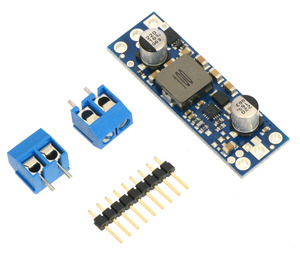
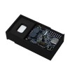
The connections are labeled on the back side of the PCB, and the board offers several options for making electrical connections. The eight smaller through-holes on the ends of the board are arranged with a 0.1" spacing for compatibility with solderless breadboards, connectors, and other prototyping arrangements that use a 0.1" grid; you can solder pieces of the included 9A—1 straight male header strip into these smaller holes. Alternatively, you can solder the included 2-pin 5mm-pitch terminal blocks to the two pairs of larger holes on the ends of the board. For the most compact installation, you can solder wires directly to the board.
Note that this regulator has a thick PCB (0.093"), so terminal block and header pins will not protrude as far through the holes as they would with typical 0.062"-thick PCBs.
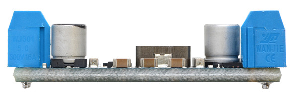 |
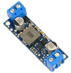
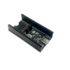
| Pololu step-up voltage regulator U3V50x with included terminal blocks installed, side view. |
|---|
The board has two mounting holes intended for #2 or M2 screws. The mounting holes are at opposite corners of the board, separated by 1.7" horizontally and 0.4" vertically.
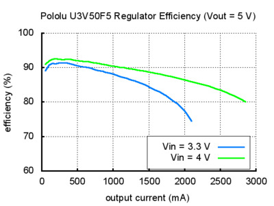
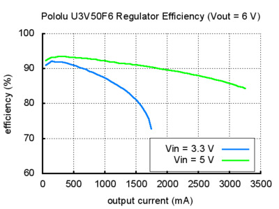
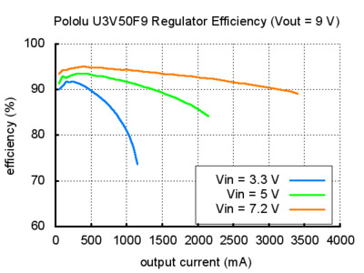
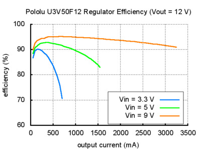
The efficiency of a voltage regulator, defined as (Power out)/(Power in), is an important measure of its performance, especially when battery life or heat are concerns. As shown in the graphs below, this switching regulator typically has an efficiency of 80 to 95%.
 |
 |
 |
 |
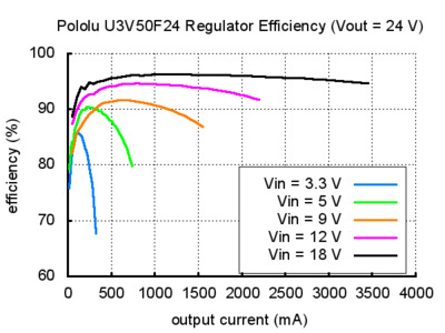 |
The maximum achievable output current is approximately proportional to the ratio of the input voltage to the output voltage. If the input current exceeds the 5 A switch current limit, the output voltage will begin to drop. Additionally, the maximum output current can depend on other factors, including the ambient temperature, air flow, and heat sinking.
During normal operation, this product can get hot enough to burn you. Take care when handling this product or other components connected to it.
Data sheet
Manufacturer BTC Korporacja sp. z o. o. Lwowska 5 05-120 Legionowo Poland sprzedaz@kamami.pl 22 767 36 20
Responsible person BTC Korporacja sp. z o. o. Lwowska 5 05-120 Legionowo Poland sprzedaz@kamami.pl 22 767 36 20
Step-Down Voltage Regulator D24V25F5. Pololu 2850
The compact (0.4″ × 0.5″) D24V5F15 synchronous buck voltage regulator takes an input voltage of up to 36 V and efficiently reduces it to 15 V while allowing for a maximum output current of 500 mA. Pololu 2847
The compact (0.4″ × 0.5″) D24V5F12 synchronous buck voltage regulator takes an input voltage of up to 36 V and efficiently reduces it to 12 V while allowing for a maximum output current of 500 mA.
The compact (0.4″ × 0.5″) D24V5F9 synchronous buck voltage regulator takes an input voltage of up to 36 V and efficiently reduces it to 9 V while allowing for a maximum output current of 500 mA. Pololu 2845
No product available!
The compact (0.4″ × 0.5″) D24V5F6 synchronous buck voltage regulator takes an input voltage of up to 36 V and efficiently reduces it to 6 V while allowing for a maximum output current of 500 mA. Pololu 2844
The compact (0.4″ × 0.5″) D24V5F5 synchronous buck voltage regulator takes an input voltage of up to 36 V and efficiently reduces it to 5 V while allowing for a maximum output current of 500 mA. Pololu 2843
The compact (0.4″ × 0.5″) D24V5F2 synchronous buck voltage regulator takes input voltages between 3 V and 36 V and efficiently reduces them to 2.5 V while allowing for a maximum output current of 500 mA. This regulator offers typical efficiencies between 80% and 90%. The pins have a 0.1″ spacing, making this board compatible with standard solderless breadboards and perfboards.
No product available!
The compact (0.4″ × 0.5″) D24V5F1 synchronous buck voltage regulator takes input voltages between 3 V and 36 V and efficiently reduces them to 1.8 V while allowing for a maximum output current of 500 mA. This regulator offers typical efficiencies between 75% and 90%. The pins have a 0.1″ spacing, making this board compatible with standard solderless breadboards and perfboards.
This small synchronous switching step-down (or buck) regulator takes an input voltage from 4 V to 36 V and efficiently reduces it to 3.3 V. The board measures only 0.7″ × 0.7″ yet delivers a typical continuous output current of up to 2.6 A and features reverse voltage protection.
This small synchronous switching step-down (or buck) regulator takes an input voltage of up to 36V and efficiently reduces it to 5V. The board measures only 0.7″ × 0.7″ yet delivers a typical continuous output current of up to 2.5A and features reverse voltage protection. Pololu 2858
The very small step-down 6 V, 2.5 A synchronous inverter can be supplied with voltage up to 36 V, dimensions: 17.8 mm x 17.8 mm. Pololu 2859
No product available!
This small synchronous switching step-down (or buck) regulator takes an input voltage of up to 36 V and efficiently reduces it to 7.5 V. The board measures only 0.7″ × 0.7″ yet delivers a typical continuous output current of up to 2.4 A and features reverse voltage protection.
No product available!
This small synchronous switching step-down (or buck) regulator takes an input voltage of up to 36 V and efficiently reduces it to 9 V. The board measures only 0.7″ × 0.7″ yet delivers a typical continuous output current of up to 2.3 A and features reverse voltage protection.
No product available!
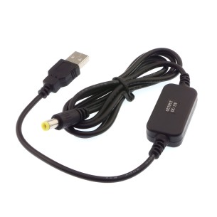
A handy way to power 12V powered devices with a center-positive 2.1mm DC barrel jack from a USB port. Adafruit 2778
No product available!
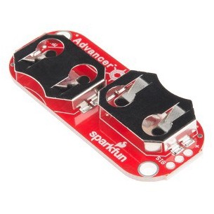
The MyoWare Power Shield is designed to take two standard CR2032 coin cell batteries to power the MyoWare Muscle Sensor. We have made this board in a way that the coin cell batteries are connected in parallel for extended capacity at a nominal 3.0V. DEV-13684
No product available!
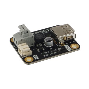
A small DC - DC boost module that converts a 0.9..5V power source to standard 5V, making it capable of supplying power to an Arduino microcontroller and other small electronic devices that use a 5v input. It integrates a PFM DC-DC boost control chip. FIT0471
Pololu 12V Step-Up Voltage Regulator U3V50F12