


zł70.40 tax excl.
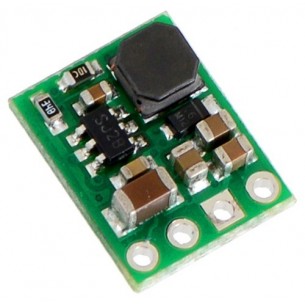
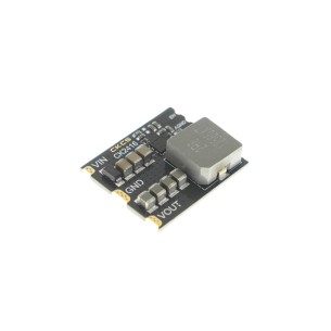
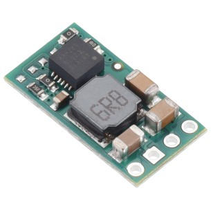
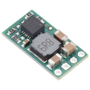
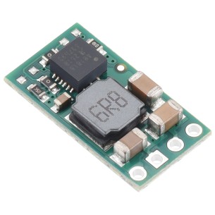
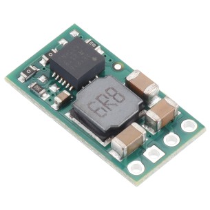
This small synchronous switching step-down (or buck) regulator takes an input voltage of up to 38 V and efficiently reduces it to 9 V. The board measures only 0.7″ × 0.7″, but it allows a typical continuous output current of up to 2.5 A. Typical efficiencies of 85% to 95% make this regulator well suited for powering moderate loads like sensors or small motors.
The D24V25Fx family of step-down voltage regulators generates lower output voltages from input voltages as high as 38 V. They are switching regulators (also called switched-mode power supplies (SMPS) or DC-to-DC converters) with typical efficiencies between 85% and 95%, which is much more efficient than linear voltage regulators, especially when the difference between the input and output voltage is large. The available output current is a function of the input voltage and efficiency (see the Typical efficiency and output current section below), but the output current can typically be as high as 2.5 A.
At light loads, the switching frequency automatically changes to maintain high efficiencies. These regulators have a typical quiescent (no load) current draw of less than 1 mA, and the ENABLE pin can be used to put the boards in a low-power state that reduces the quiescent current to approximately 10 µA to 20 µA per volt on VIN.
The modules have built-in reverse-voltage protection, short-circuit protection, a thermal shutdown feature that helps prevent damage from overheating, and a soft-start feature that reduces inrush current.
The different voltage versions of this regulator all look very similar, so you should consider adding your own distinguishing marks or labels if you will be working simultaneously with multiple versions. This product page applies to all versions of the D24V25Fx family.
For newer, lower-priced step-down regulators with a similar input voltage range, output current, and size, consider the D24V22Fx family of regulators. Please note that while these D24V22Fx regulators look very similar to the D24V25Fx family of regulators, they do not have the same pinout and are based on a different internal design, so there are fundamental differences in operation. The D24V22Fx family also includes a 12 V option while the D24V25Fx family does not.
For higher-power applications, we carry a slightly larger, pin-compatible, 5 V version of this regulator that has a typical maximum output current of 5 A.
Two even larger, higher-power, 5 V versions of this regulator are also available: one with a typical maximum output current of 6 A, and the other with a typical maximum output current of 9 A. The higher-power versions also have a few additional features, like a “power good” signal and the ability to lower their output voltage, and they include optional terminal blocks for easy removable connections.
This buck regulator has five connection points for four different connections: enable (EN), input voltage (VIN), 2x ground (GND), and output voltage (VOUT).
The input voltage, VIN, powers the regulator. Voltages between 4.5 V and 38 V can be applied to VIN, but for versions of the regulator that have an output voltage higher than 4.5 V, the effective lower limit of VIN is VOUT plus the regulator’s dropout voltage, which varies approximately linearly with the load (see below for graphs of dropout voltages as a function of the load).
The output voltage, VOUT, is fixed and depends on the regulator version: the D24V25F3 version outputs 3.3 V, the D24V25F5 version outputs 5 V, the D24V25F6 version outputs 6 V, the D24V25F7 version outputs 7.5 V, and the D24V5F9 version outputs 9 V.
The regulator is enabled by default: a 100 kΩ pull-up resistor on the board connects the ENABLE pin to reverse-protected VIN. The ENABLE pin can be driven low (under 0.6 V) to put the board into a low-power state. The quiescent current draw in this sleep mode is dominated by the current in the pull-up resistor from ENABLE to VIN and by the reverse-voltage protection circuit, which will draw between 10 µA and 20 µA per volt on VIN when ENABLE is held low. If you do not need this feature, you should leave the ENABLE pin disconnected.
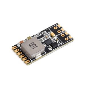
The five connection points are labeled on the top of the PCB and are arranged with a 0.1″ spacing for compatibility with solderless breadboards, connectors, and other prototyping arrangements that use a 0.1″ grid. Either the included 5×1 straight male header strip or the 5×1 right angle male header strip can be soldered into these holes. For the most compact installation, you can solder wires directly to the board.
The board has two 0.086″ mounting holes intended for #2 or M2 screws. The mounting holes are at opposite corners of the board and are separated by 0.53″ both horizontally and vertically.
The efficiency of a voltage regulator, defined as (Power out)/(Power in), is an important measure of its performance, especially when battery life or heat are concerns. This family of switching regulators typically has an efficiency of 85% to 95%, though the actual efficiency in a given system depends on input voltage, output voltage, and output current. See the efficiency graph near the bottom of this page for more information.
The maximum achievable output current is typically around 2.5 A, but this depends on many factors, including the ambient temperature, air flow, heat sinking, and the input and output voltage.
The dropout voltage of a step-down regulator is the minimum amount by which the input voltage must exceed the regulator’s target output voltage in order to ensure the target output can be achieved. For example, if a 5 V regulator has a 1 V dropout voltage, the input must be at least 6 V to ensure the output is the full 5 V. Generally speaking, the dropout voltage increases as the output current increases. See the “Details” section below for more information on the dropout voltage for this specific regulator version.
The regulator generally operates at a switching frequency of around 600 kHz, but the frequency drops when encountering a light load to improve efficiency. This could make it harder to filter out noise on the output caused by switching.
During normal operation, this product can get hot enough to burn you. Take care when handling this product or other components connected to it.
The over-current limit of the regulator operates on a combination of current and temperature: the current threshold decreases as the regulator temperature goes up. However, there might be some operating points at low input voltages and high output currents (well over 2.5 A) where the current is just under the limit and the regulator might not shut off before damage occurs. If you are using this regulator in an application where the input voltage is near the lower limit and the load could exceed 3.5A for sustained periods (more than five seconds), consider using additional protective components such as fuses or circuit breakers.
| Size: | 0.7″ × 0.7″ × 0.35″1 |
|---|---|
| Weight: | 2.6 g1 |
| Minimum operating voltage: | 10.5 V2 |
|---|---|
| Maximum operating voltage: | 38 V |
| Continuous output current: | 2.5 A3 |
| Output voltage: | 9 V |
| Reverse voltage protection?: | Y |
| Maximum quiescent current: | 1.2 mA4 |
| PCB dev codes: | reg15a |
|---|---|
| Other PCB markings: | 0J8475 |
Data sheet
Manufacturer BTC Korporacja sp. z o. o. Lwowska 5 05-120 Legionowo Poland sprzedaz@kamami.pl 22 767 36 20
Responsible person BTC Korporacja sp. z o. o. Lwowska 5 05-120 Legionowo Poland sprzedaz@kamami.pl 22 767 36 20
The Step-Down D24V3F9 Buck Voltage Regulator module gives the output voltage of 9V with a wide input voltage range of 11-42V and a maximum output current of 300 mA. Pololu 2099
No product available!
The Step-Down D24V6F9 Buck Voltage Regulator module gives the output voltage of 9V with a wide input voltage range of 11.5-42V and a maximum output current of 600 mA. Pololu 2108
No product available!
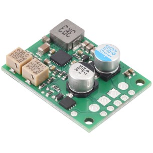
Efficient step-down converter that reduces the input voltage from up to 45 V to a regulated output voltage range from 1.4 to 7 V, offering high efficiency and a maximum continuous current of 3.8 A. It has built-in protection against reverse polarity, overload and short circuit, and the spread spectrum function reduces EMI interference. The module is equipped with an additional potentiometer for adjusting the cut-off voltage. Pololu 4852
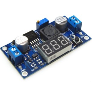
The LM2596 module with an adjustable step-down converter is a versatile tool for powering and testing electronic circuits. It allows convenient voltage adjustment with precise parameter monitoring thanks to the built-in voltmeter. Ideal for prototyping, laboratory experiments, and service work.
No product available!
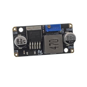
The DC-DC Step-down Converter Module with the LM2596S chip allows you to convert the voltage from the range of 3-40 V to a regulated output voltage of 1.5-35 V with high efficiency up to 92%. The maximum output current is 3 A, and the operating frequency is 150 kHz. The compact design with dimensions of 43 × 21 × 14 mm, the possibility of precise voltage regulation and a pinout of 2.54 mm facilitate the integration of the module in DIY projects, power supply systems, modeling and laboratory stations. The operating temperature range is from -40 to 85°C
DC-DC step-down converter module 12V 12A used to convert energy from 15-24V input voltage to stable 12V, providing up to 12A current. Thanks to high conversion efficiency (over 90%) and low ripple (<50mV), it is ideal for powering sensitive devices in applications such as robotics, drones or LED lighting systems. Additionally, built-in overheating and short-circuit protection mechanisms ensure reliable operation even in difficult conditions. DFRobot DFR1208
DC-DC step-down converter module 5V 16A used to convert energy from 6-24V input voltage to stable 5V, providing up to 16A current. Thanks to high conversion efficiency (over 90%) and low ripple (<20mV), it is ideal for powering sensitive devices in applications such as robotics, drones or LED lighting systems. Additionally, built-in overheating and short-circuit protection mechanisms ensure reliable operation even in difficult conditions. DFRobot DFR1202
The DC-DC Buck Converter DC5-36-TO-DC3V3-5 in SMD version is designed for direct surface mounting. With selectable output voltage and high efficiency, it is suitable for applications involving microcontrollers, IoT systems, and mobile electronic devices.
No product available!
DC-DC Buck Converter 5–36 V with 5 V or 3.3 V output in the DC5-36-TO-DC3V3-5-M version is equipped with terminal and pin headers for quick deployment in power applications. High efficiency, adjustable voltage, and compact size make it suitable for powering microcontrollers, communication modules, and embedded systems.
No product available!
Miniature 15 V switching voltage regulator based on the AP63200 IC, input range 3.5 - 32 V, output current up to 1 A (1.5 A peak), efficiency up to 90%, dimensions 18 x 11 mm. KAmod-DCDC-AP63200 15V
Miniature Step-Down converter module with AP63300, input voltage 3.5-32 V, selectable output voltage 3.3 V, 5 V or 12 V, maximum continuous current 1 A, peak current up to 2 A, dimensions 24 x 16 mm. Kamami KAmod DCDC AP63300
Step-down voltage regulator module based on the APM81815 providing a fixed 3.3 V output at up to 1.1 A with an input voltage range of 5 - 72 V. Pololu 5266
Step-down voltage regulator module based on the APM81815 providing a fixed 5 V output at up to 1.1 A with an input voltage range of 5.05 - 72 V. Pololu 5267
No product available!
Step-down voltage regulator module based on the APM81815 providing a fixed 5.35 V output at up to 1.1 A with an input voltage range of 5.4 - 72 V. Pololu 5268
No product available!
Step-down voltage regulator module based on the APM81815 providing a fixed 12 V output at up to 0.8 A with an input voltage range of 12.1 - 72 V. Pololu 5269
Miniature 2.5 V switching voltage regulator based on the AP63200 converter, input range 3.5 – 32 V, output current up to 1 A (1.5 A peak), efficiency up to 90%, dimensions 18 x 11 mm. KAmod-DCDC-AP63200 2.5V
Miniature 3.3 V switching voltage regulator based on the AP63200 converter, input range 3.5 – 32 V, output current up to 1 A (1.5 A peak), efficiency up to 90%, dimensions 18 x 11 mm. KAmod-DCDC-AP63200 3.3V
Miniature 4.2 V switching voltage regulator based on the AP63200 IC, input range 3.5 – 32 V, output current up to 1 A (1.5 A peak), efficiency up to 90%, dimensions 18 x 11 mm. KAmod-DCDC-AP63200 4.2V
This small synchronous switching step-down (or buck) regulator takes an input voltage of up to 38 V and efficiently reduces it to 9 V. The board measures only 0.7″ × 0.7″, but it allows a typical continuous output current of up to 2.5 A. Typical efficiencies of 85% to 95% make this regulator well suited for powering moderate loads like sensors or small motors.