


zł114.02 tax excl.
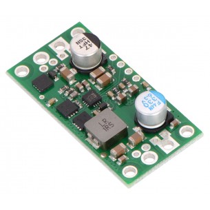
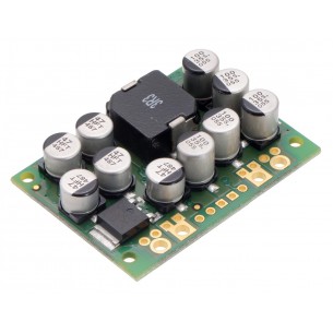
This synchronous switching step-down (or buck) regulator takes an input voltage of up to 38 V and efficiently reduces it to 5 V with an available output current of around 9 A.
These high-current step-down (buck) regulators generate a fixed 5 V output from input voltages up to 38 V. They are switching regulators (also called switched-mode power supplies (SMPS) or DC-to-DC converters) and have a typical efficiency between 80% to 95%. The available output current is a function of the input voltage and efficiency (see the Typical Efficiency and Output Current section below), but the output current can typically be as high as 9 A.
A very similar version of this regulator is available with a typical maximum output current of 6 A. The two versions of the board are difficult to tell apart visually, so the bottom silkscreen includes a blank space where you can add your own distinguishing marks or labels. You should not use the colors of the printing on the tall, cylindrical electrolytic capacitors to differentiate the two versions as these colors are subject to change. We also carry two much smaller versions of this regulator, one with a typical maximum output current of 2.5 A and one with a typical maximum output current of 5 A.
The ENABLE pin can be used to put the board in a low-power state that reduces the quiescent current to approximately 10 µA to 20 µA per volt on VIN, and a PG (power good) indicator makes it easy to monitor the state of the main power for your system. The regulator’s output voltage setting can also be lowered by adding an external resistor.
This regulator has built-in reverse-voltage protection, short-circuit protection, thermal shutdown (which typically activates at 160°C), a soft-start feature that reduces inrush current, and an under-voltage lockout that causes the regulator to turn off when the input voltage is below 4.2 V (typical).
This buck regulator has six connections: input voltage (VIN), ground (GND), output voltage (VOUT), feedback (FB), ENABLE, and power good (PG).
The input voltage, VIN, powers the regulator and can be supplied with voltages up to 38V. The effective lower limit of VIN is VOUT plus the regulator’s dropout voltage, which varies approximately linearly with the load from around 500 mV to 1.5 V (see below for a graph of the dropout voltage as a function of the load).
The output voltage, VOUT, is set to 5V by default. The output voltage can optionally be lowered by adding a resistor between the FB pin and VOUT as detailed in the Decreasing the output voltage section below.
The regulator is enabled by default: a 100 kΩ pull-up resistor on the board connects the ENABLE pin to reverse-protected VIN. The ENABLE pin can be driven low (under 0.6 V) to put the board into a low-power state. The quiescent current draw in this sleep mode is dominated by the current in the pull-up resistor from ENABLE to VIN and by the reverse-voltage protection circuit, which will draw between 10 µA and 20 µA per volt on VIN when ENABLE is held low. If you do not need this feature, you should leave the ENABLE pin disconnected.
The “power good” indicator, PG, is an open-drain output that goes low when the regulator’s output voltage falls below 90% of what it is set to (i.e. 4.5 V with the default 5 V output setting). An external pull-up resistor is required to use this pin.
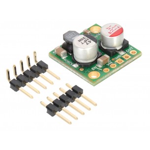
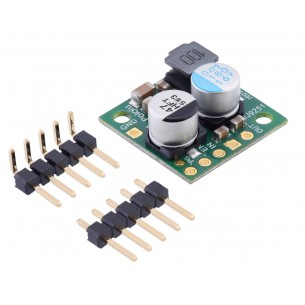
The connections are labeled on the back side of the PCB, and the board offers several options for making electrical connections. The eight smaller through-holes on the ends of the board are arranged with a 0.1″ spacing for compatibility with solderless breadboards, connectors, and other prototyping arrangements that use a 0.1″ grid; you can solder pieces of the included 12×1 straight male header strip into these smaller holes. Alternatively, you can solder the included 2-pin 5mm-pitch terminal blocks to the two pairs of larger holes on the ends of the board. For the most compact installation, you can solder wires directly to the board.
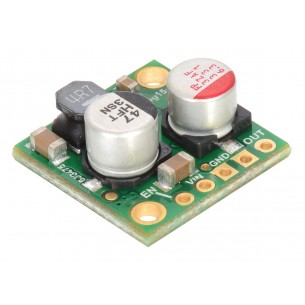
The board has four 0.086″ mounting holes intended for #2 or M2 screws. The mounting holes are in the four corners of the board and are separated by 1.4″ horizontally and 0.6″ vertically. In applications where mounting screws are not used and wires are soldered directly to the board, the insulated part of the wires can be passed through the mounting holes for strain relief. The picture above shows an example of this with the lower-power D24V60F5 and 20 AWG wire, which was close to the limit of what would fit through the mounting holes.
The set voltage can optionally be decreased by adding an external resistor between the FB and the neighboring VOUT pin. The equations below show how the output voltage relates to the value of an external resistor, R:
VOUT=((5.24⋅R):(16.2 kΩ+R)+1)⋅0,8V
R=(VOUT–0.8 V):(5 V–VOUT)⋅16.2 kΩ
For example, to get an output voltage of 3.3 V, you could put a 23.7 kΩ resistor between FB and VOUT.
The minimum VOUT for this regulator is 0.8 V. Please note that the small VOUT pin next to FB is not intended to source much current; its purpose is to provide a convenient spot for connecting a voltage-adjustment resistor.
The efficiency of a voltage regulator, defined as (Power out)/(Power in), is an important measure of its performance, especially when battery life or heat are concerns. As shown in the graph below, these switching regulators have an efficiency of 80% to 95% for most combinations of input voltage, and load.
The maximum achievable output current of the board depends on many factors, including the ambient temperature, air flow, heat sinking, and the input and output voltage. The graph below shows the maximum continuous output current this regulator can deliver with no external heat sinking or added air flow.
During normal operation, this product can get hot enough to burn you. Take care when handling this product or other components connected to it.
The dropout voltage of a step-down regulator is the minimum amount by which the input voltage must exceed the regulator’s target output voltage in order to ensure the target output can be achieved. For example, if a 5 V regulator has a 1 V dropout voltage, the input must be at least 6 V to ensure the output is the full 5 V. The following graph shows the dropout voltage for the D24V60F5 regulator as a function of the output current:
The regulator generally operates at a switching frequency of around 470 kHz, but the frequency drops when encountering a light load to improve efficiency. This could make it harder to filter out noise on the output caused by switching. This also causes small variations in the output voltage like those shown in the graph below:
| Size: | 1.6″ × 0.8″ × 0.3″1 |
|---|---|
| Weight: | 4.8 g1 |
| Minimum operating voltage: | 5 V |
|---|---|
| Maximum operating voltage: | 38 V |
| Continuous output current: | 9 A2 |
| Output voltage: | 5 V |
| Reverse voltage protection?: | Y |
| Maximum quiescent current: | 15 mA3 |
| PCB dev codes: | reg15b |
|---|---|
| Other PCB markings: | 0J8008, blank white box |
Data sheet
Manufacturer BTC Korporacja sp. z o. o. Lwowska 5 05-120 Legionowo Poland sprzedaz@kamami.pl 22 767 36 20
Responsible person BTC Korporacja sp. z o. o. Lwowska 5 05-120 Legionowo Poland sprzedaz@kamami.pl 22 767 36 20
Pololu 5V Step-Up/Step-Down Voltage Regulator S7V7F5
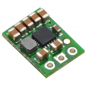
The Step-Up/Step-DownS7V8F5 Buck Voltage Regulator module with output voltage 5V, input voltage range of 2.7-11.8V and a maximum output current of 0.5-1A. Pololu 2123
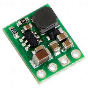
The Step-Down D24V6F5 Buck Voltage Regulator module gives the output voltage of 5V with a wide input voltage range of 7-42V and a maximum output current of 600 mA. Pololu 2107
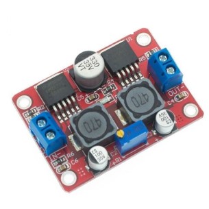
A DC-DC voltage converter, based on a combination of an LM2577S Step-Up converter and an LM2596S Step-Down converter. The input voltage can range from 3.5 V to 28 V, and the output voltage is adjustable from 1.25 V to 26 V
No product available!
This synchronous switching step-down (or buck) regulator takes an input voltage of up to 38 V and efficiently reduces it to 5 V with an available output current of around 9 A.
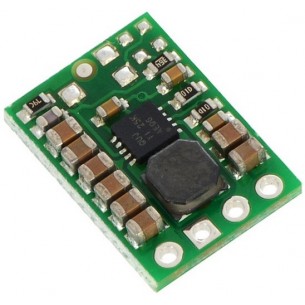
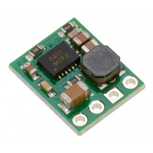
This small synchronous switching step-down (or buck) regulator takes an input voltage of up to 38 V and efficiently reduces it to 5 V. The board measures only 0.7″ × 0.8″, but it allows a typical continuous output current of up to 5 A. Typical efficiencies of 85% to 95% make this regulator well suited for high-power applications like powering motors or servos.
Step-Down Voltage Regulator D24V25F5. Pololu 2850
The compact (0.4″ × 0.5″) D24V5F15 synchronous buck voltage regulator takes an input voltage of up to 36 V and efficiently reduces it to 15 V while allowing for a maximum output current of 500 mA. Pololu 2847
The compact (0.4″ × 0.5″) D24V5F12 synchronous buck voltage regulator takes an input voltage of up to 36 V and efficiently reduces it to 12 V while allowing for a maximum output current of 500 mA.
The compact (0.4″ × 0.5″) D24V5F9 synchronous buck voltage regulator takes an input voltage of up to 36 V and efficiently reduces it to 9 V while allowing for a maximum output current of 500 mA. Pololu 2845
No product available!
The compact (0.4″ × 0.5″) D24V5F6 synchronous buck voltage regulator takes an input voltage of up to 36 V and efficiently reduces it to 6 V while allowing for a maximum output current of 500 mA. Pololu 2844
The compact (0.4″ × 0.5″) D24V5F5 synchronous buck voltage regulator takes an input voltage of up to 36 V and efficiently reduces it to 5 V while allowing for a maximum output current of 500 mA. Pololu 2843
The compact (0.4″ × 0.5″) D24V5F2 synchronous buck voltage regulator takes input voltages between 3 V and 36 V and efficiently reduces them to 2.5 V while allowing for a maximum output current of 500 mA. This regulator offers typical efficiencies between 80% and 90%. The pins have a 0.1″ spacing, making this board compatible with standard solderless breadboards and perfboards.
No product available!
The compact (0.4″ × 0.5″) D24V5F1 synchronous buck voltage regulator takes input voltages between 3 V and 36 V and efficiently reduces them to 1.8 V while allowing for a maximum output current of 500 mA. This regulator offers typical efficiencies between 75% and 90%. The pins have a 0.1″ spacing, making this board compatible with standard solderless breadboards and perfboards.
This small synchronous switching step-down (or buck) regulator takes an input voltage from 4 V to 36 V and efficiently reduces it to 3.3 V. The board measures only 0.7″ × 0.7″ yet delivers a typical continuous output current of up to 2.6 A and features reverse voltage protection.
This small synchronous switching step-down (or buck) regulator takes an input voltage of up to 36V and efficiently reduces it to 5V. The board measures only 0.7″ × 0.7″ yet delivers a typical continuous output current of up to 2.5A and features reverse voltage protection. Pololu 2858
The very small step-down 6 V, 2.5 A synchronous inverter can be supplied with voltage up to 36 V, dimensions: 17.8 mm x 17.8 mm. Pololu 2859
No product available!
This small synchronous switching step-down (or buck) regulator takes an input voltage of up to 36 V and efficiently reduces it to 7.5 V. The board measures only 0.7″ × 0.7″ yet delivers a typical continuous output current of up to 2.4 A and features reverse voltage protection.
No product available!
This small synchronous switching step-down (or buck) regulator takes an input voltage of up to 36 V and efficiently reduces it to 9 V. The board measures only 0.7″ × 0.7″ yet delivers a typical continuous output current of up to 2.3 A and features reverse voltage protection.
No product available!
Step-Down DC-DC converter module based on the D24V150F9 chip. Input voltage 11 ... 40V, output voltage 9V (max 15A). Pololu 2884
This synchronous switching step-down (or buck) regulator takes an input voltage of up to 38 V and efficiently reduces it to 5 V with an available output current of around 9 A.