


zł43.12 tax excl.
Pololu 2834
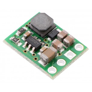
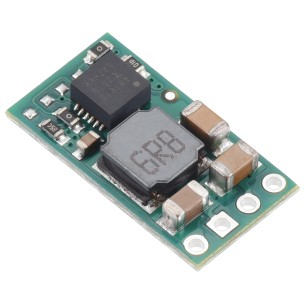
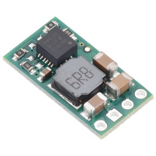
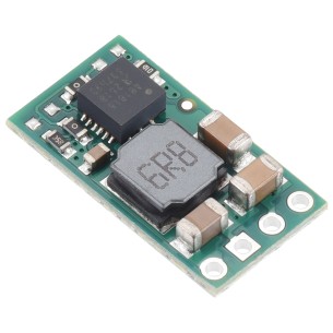
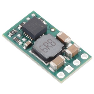
Pololu 12V, 1A Step-Down Voltage Regulator D24V10F12
The compact (0.5″ × 0.7″) D24V10F12 synchronous buck voltage regulator takes an input voltage of up to 36 V and efficiently reduces it to 12 V while allowing for a maximum output current of 1 A. This regulator offers typical efficiencies between 85% and 93% and has a very low dropout, so it can be used with input voltages as low as a few hundred millivolts above 12 V. The pins have a 0.1″ spacing, making this board compatible with standard solderless breadboards and perfboards.
Description
The D24V10Fx family of step-down voltage regulators features the Intersil ISL85410 1A synchronous buck regulator and generates lower output voltages from input voltages as high as 36 V. They are switching regulators (also called switched-mode power supplies (SMPS) or DC-to-DC converters) with typical efficiencies between 80% and 93%, which is much more efficient than linear voltage regulators, especially when the difference between the input and output voltage is large. These regulators have a power-save mode that activates at light loads and a low quiescent (no load) current draw, which make them well suited for applications that are run from a battery.
The different versions of this regulator all look very similar, so the bottom silkscreen includes a blank space where you can add your own distinguishing marks or labels. This product page applies to all five versions of the D24V10Fx family.
The SHDN pin can be used to put the board in a low-power state that reduces the quiescent current to approximately 10 µA to 20 µA per volt on VIN, and a PG (power good) output can be used to monitor the state of the regulator’s output voltage.
The regulators feature short-circuit/over-current protection, and thermal shutdown helps prevent damage from overheating. The boards do not have reverse-voltage protection.
Features
Connections
The buck regulator has five connections: power good (PG). shutdown (SHDN), input voltage (VIN), ground (GND), and output voltage (VOUT).
The “power good” indicator, PG, is an open-drain output that drives low when the regulator’s output voltage falls below 80% or rises above 120% of its target output voltage. This output is also actively held low for the duration of the regulator’s 2 ms soft-start period and while the regulator is being disabled by the SHDN input or by over-temperature or over-current fault conditions. An external pull-up resistor is generally required to use this pin.
The SHDN pin can be driven low (under 0.4 V) to turn off the output and put the board into a low-power state. There is a 100 kΩ pull-up resistor between the SHDN pin and VIN, so if you want to leave the board permanently enabled, the SHDN pin can be left disconnected. While the SHDN pin is being driven low, the current draw of the regulator is dominated by the current through the pull-up resistor and will be proportional to the input voltage. (At 36 V in it will draw about 360 μA.)
The input voltage, VIN, powers the regulator. Voltages between 3 V and 36 V can be applied to VIN, but the effective lower limit of VIN is VOUT plus the regulator’s dropout voltage, which varies approximately linearly with the load (see below for graphs of dropout voltages as a function of the load). Additionally, please be wary of destructive LC spikes (see below for more information).
The output voltage, VOUT, is fixed and depends on the regulator version: the D24V10F3 version outputs 3.3 V, the D24V10F5 version outputs 5 V, the D24V10F6 version outputs 6 V, the D24V10F9 version outputs 9 V, and the D24V10F12 version outputs 12 V.
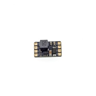
The five connections are labeled on the back side of the PCB and are arranged with a 0.1″ spacing along the edge of the board for compatibility with solderless breadboards, connectors, and other prototyping arrangements that use a 0.1″ grid. You can solder wires directly to the board or solder in either the 5×1 straight male header strip or the 5×1 right-angle male header strip that is included.
Typical efficiency and output current
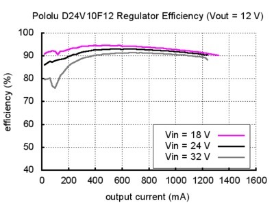
The efficiency of a voltage regulator, defined as (Power out)/(Power in), is an important measure of its performance, especially when battery life or heat are concerns. This family of switching regulators typically has an efficiency of 80% to 93%, though the actual efficiency in a given system depends on input voltage, output voltage, and output current. See the efficiency graph near the bottom of this page for more information.
In order to achieve a high efficiency at low loads, this regulator automatically goes into a power-save mode where the switching frequency is reduced. In power-save mode, the switching frequency of the regulator changes as necessary to minimize power loss. This could make it harder to filter out noise on the output caused by switching.
Typical dropout voltage
The dropout voltage of a step-down regulator is the minimum amount by which the input voltage must exceed the regulator’s target output voltage in order to ensure the target output can be achieved. For example, if a 5 V regulator has a 1 V dropout voltage, the input must be at least 6 V to ensure the output is the full 5 V. Generally speaking, the dropout voltage increases as the output current increases. See the “Details” section below for more information on the dropout voltage for this specific regulator version.
Details for item #2834
The graphs below show the typical efficiency and dropout voltage of the 12 V D24V10F12 regulator as a function of the output current:
.jpg)
Specifications
Download
Data sheet
Manufacturer BTC Korporacja sp. z o. o. Lwowska 5 05-120 Legionowo Poland sprzedaz@kamami.pl 22 767 36 20
Responsible person BTC Korporacja sp. z o. o. Lwowska 5 05-120 Legionowo Poland sprzedaz@kamami.pl 22 767 36 20
Step-Down DC-DC converter module based on the D36V6F12 system. Input voltage 12.2.50V, output voltage 12V (max. 600mA). Pololu 3796
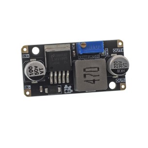
The DC-DC Step-down Converter Module with the LM2596S chip allows you to convert the voltage from the range of 3-40 V to a regulated output voltage of 1.5-35 V with high efficiency up to 92%. The maximum output current is 3 A, and the operating frequency is 150 kHz. The compact design with dimensions of 43 × 21 × 14 mm, the possibility of precise voltage regulation and a pinout of 2.54 mm facilitate the integration of the module in DIY projects, power supply systems, modeling and laboratory stations. The operating temperature range is from -40 to 85°C
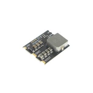
DC-DC step-down converter module 12V 12A used to convert energy from 15-24V input voltage to stable 12V, providing up to 12A current. Thanks to high conversion efficiency (over 90%) and low ripple (<50mV), it is ideal for powering sensitive devices in applications such as robotics, drones or LED lighting systems. Additionally, built-in overheating and short-circuit protection mechanisms ensure reliable operation even in difficult conditions. DFRobot DFR1208
DC-DC step-down converter module 5V 16A used to convert energy from 6-24V input voltage to stable 5V, providing up to 16A current. Thanks to high conversion efficiency (over 90%) and low ripple (<20mV), it is ideal for powering sensitive devices in applications such as robotics, drones or LED lighting systems. Additionally, built-in overheating and short-circuit protection mechanisms ensure reliable operation even in difficult conditions. DFRobot DFR1202
The DC-DC Buck Converter DC5-36-TO-DC3V3-5 in SMD version is designed for direct surface mounting. With selectable output voltage and high efficiency, it is suitable for applications involving microcontrollers, IoT systems, and mobile electronic devices.
No product available!
DC-DC Buck Converter 5–36 V with 5 V or 3.3 V output in the DC5-36-TO-DC3V3-5-M version is equipped with terminal and pin headers for quick deployment in power applications. High efficiency, adjustable voltage, and compact size make it suitable for powering microcontrollers, communication modules, and embedded systems.
No product available!
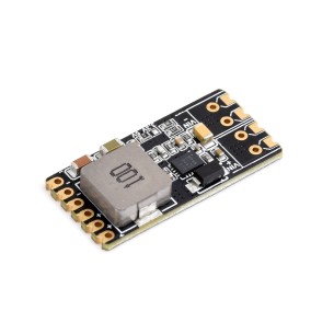
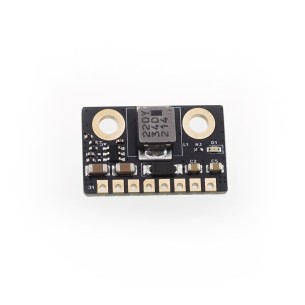
Miniature 15 V switching voltage regulator based on the AP63200 IC, input range 3.5 - 32 V, output current up to 1 A (1.5 A peak), efficiency up to 90%, dimensions 18 x 11 mm. KAmod-DCDC-AP63200 15V
Miniature Step-Down converter module with AP63300, input voltage 3.5-32 V, selectable output voltage 3.3 V, 5 V or 12 V, maximum continuous current 1 A, peak current up to 2 A, dimensions 24 x 16 mm. Kamami KAmod DCDC AP63300
Step-down voltage regulator module based on the APM81815 providing a fixed 3.3 V output at up to 1.1 A with an input voltage range of 5 - 72 V. Pololu 5266
Step-down voltage regulator module based on the APM81815 providing a fixed 5 V output at up to 1.1 A with an input voltage range of 5.05 - 72 V. Pololu 5267
No product available!
Step-down voltage regulator module based on the APM81815 providing a fixed 5.35 V output at up to 1.1 A with an input voltage range of 5.4 - 72 V. Pololu 5268
No product available!
Step-down voltage regulator module based on the APM81815 providing a fixed 12 V output at up to 0.8 A with an input voltage range of 12.1 - 72 V. Pololu 5269
Miniature 2.5 V switching voltage regulator based on the AP63200 converter, input range 3.5 – 32 V, output current up to 1 A (1.5 A peak), efficiency up to 90%, dimensions 18 x 11 mm. KAmod-DCDC-AP63200 2.5V
Miniature 3.3 V switching voltage regulator based on the AP63200 converter, input range 3.5 – 32 V, output current up to 1 A (1.5 A peak), efficiency up to 90%, dimensions 18 x 11 mm. KAmod-DCDC-AP63200 3.3V
Miniature 4.2 V switching voltage regulator based on the AP63200 IC, input range 3.5 – 32 V, output current up to 1 A (1.5 A peak), efficiency up to 90%, dimensions 18 x 11 mm. KAmod-DCDC-AP63200 4.2V
Miniature 5 V switching voltage regulator based on the AP63200 IC, input range 3.5 – 32 V, output current up to 1 A (1.5 A peak), efficiency up to 90%, dimensions 18 x 11 mm. KAmod-DCDC-AP63200 5V
Miniature 8.4 V switching voltage regulator based on the AP63200 IC, input range 3.5 - 32 V, output current up to 1 A (1.5 A peak), efficiency up to 90%, dimensions 18 x 11 mm. KAmod-DCDC-AP63200 8,4V
Pololu 2834